Plasma display and method for driving the same
a plasma display and plasma technology, applied in the direction of instruments, static indicating devices, etc., can solve the problems of voltage drop, unnecessarily accumulating electric charges, and inability to sustain the discharge and eventually come to a stop, so as to control the variance in luminance and display gradation, good picture quality, and low electricity consumption
- Summary
- Abstract
- Description
- Claims
- Application Information
AI Technical Summary
Benefits of technology
Problems solved by technology
Method used
Image
Examples
first embodiment
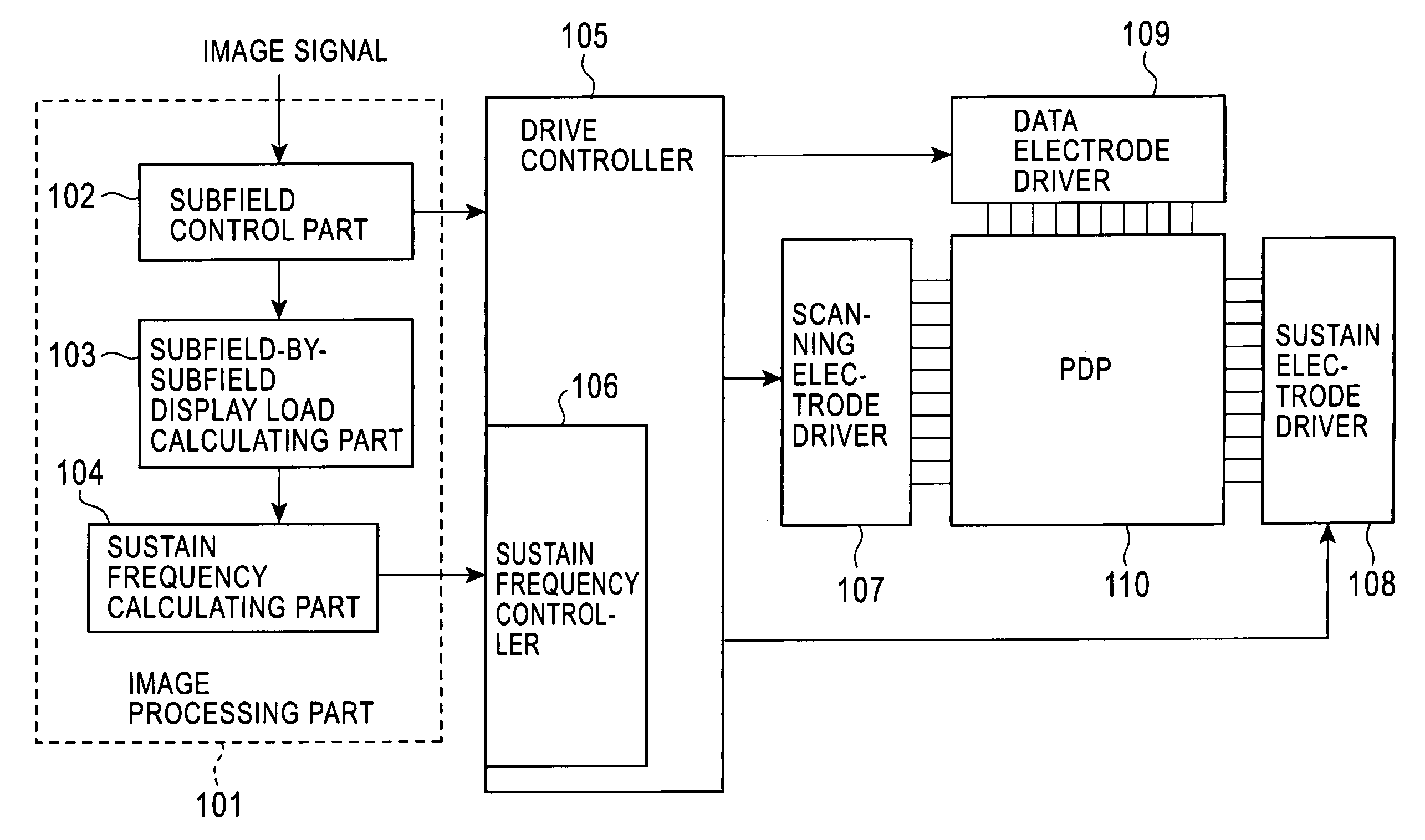
[0067] Next, an operation of the first embodiment will be described. An image signal supplied to the image processing part 101 is converted into data to be displayed on a plasma display panel with respective to each of the subfields in the subfield control part 102 within the image processing part 101. Then, from the display data for the respective subfields, the subfield-by-subfield display load calculating part 103 calculates display load amount allocated to each of the subfields. Based on data of the display load amount, the sustain frequency calculating part 104 calculates optimum frequencies for the respective subfields. The sustain frequency controller 106 within the driver controller 105 generates sustain pulse voltage data based on the sustain frequency for each of the subfields. The driver controller 105 supplies a sustain pulse waveform based on the sustain frequency for the respective subfields generated in the sustain frequency controller 106 to the scanning electrode dr...
second embodiment
[0085] To the contrary, in the second embodiment, the sustain pulse voltage is always fixed at the sustain potential and the ground potential after the electric recovery is completed. Therefore, reactive power is not increased, and no overshoot or undershoot occurs. Thus, a PDP which is low cost and has improved picture quality can be provided.
[0086] Next, a third embodiment of the present invention will be described. FIG. 14 is a circuit diagram showing the third embodiment. The circuit of this embodiment employs a self-recovery method as an electric power recovery system. Similar to the second embodiment, the embodiment is equipped with a plurality of electric power recovery circuits, and therefore, similar effect as that of the second embodiment can be obtained from this electric power recovery method.
[0087] Similar to the second embodiment, this embodiment has more than two electric power recovery circuits which have recovery coils having different inductances. FIG. 14 shows a ...
PUM
 Abstract
Description
Claims
Application Information
 - R&D
- Intellectual Property
- Life Sciences
- Materials
- Tech Scout
- Unparalleled Data Quality
- Higher Quality Content
- 60% Fewer Hallucinations
Browse by: Latest US Patents, China's latest patents, Technical Efficacy Thesaurus, Application Domain, Technology Topic, Popular Technical Reports.
© 2025 PatSnap. All rights reserved.Legal|Privacy policy|Modern Slavery Act Transparency Statement|Sitemap|About US| Contact US: help@patsnap.com


