Image display device and method of driving image display device

Inactive Publication Date: 2005-10-06
JAPAN DISPLAY WEST
View PDF9 Cites 62 Cited by
  • Summary
  • Abstract
  • Description
  • Claims
  • Application Information

AI Technical Summary

Benefits of technology

[0148] In the second embodiment, each picture element may repeat, for example, a transition to light emission, then photo-detection, and then light shutoff (“light emission→photo-detection→light shutoff”) to sense light emitted from an adjacent picture element, as in the case of the first embo

Problems solved by technology

However, this technique has the problem of raising product cost, which is caused by a component count rising due to the need for input and other devices aside from a display device.
The technique also has the problem of impairing intuitive operation, as compared to the display device including the touch panel.
Moreover, the display device including the touch panel has the problem of raising product cost, which is caused by a component count rising due to the attachment of the touch panel to a display screen.
This display device also has the problem of image degradation, whic

Method used


Image

  • Image display device and method of driving image display device
  • Image display device and method of driving image display device
  • Image display device and method of driving image display device

Examples


first embodiment

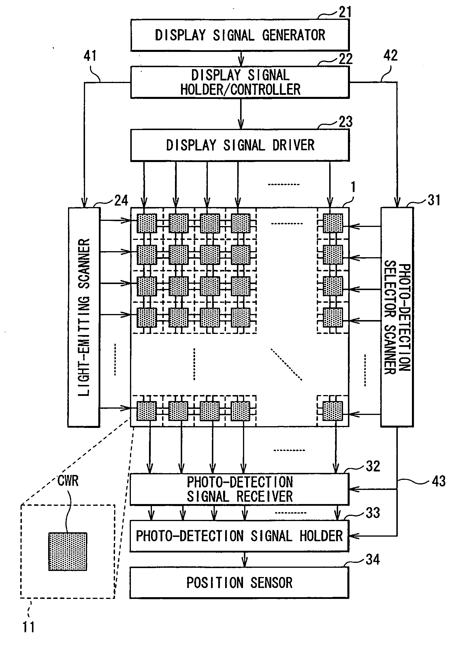
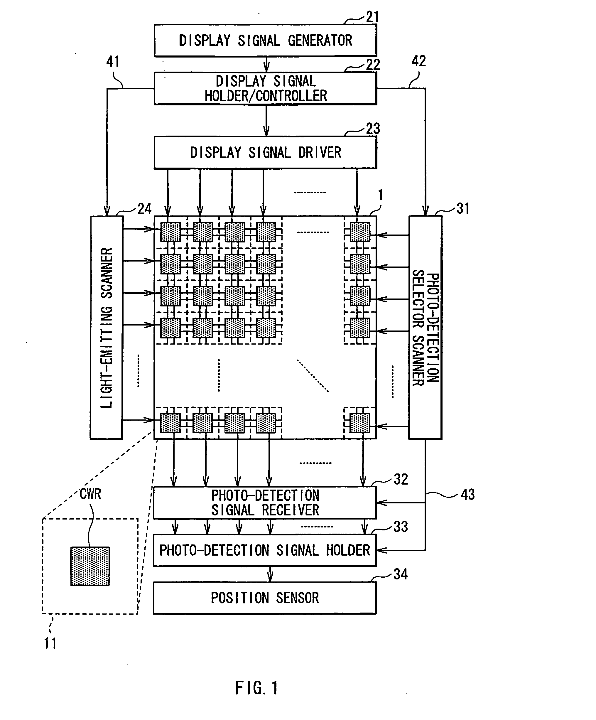
[0094]FIG. 1 shows the general configuration of an image display device according to a first embodiment of the invention.

[0095] The image display device of the first embodiment includes a display 1, a display signal generator 21, a display signal holder / controller 22, a display signal driver 23, a light-emitting scanner 24, a photo-detection signal selector scanner 31, a photo-detection signal receiver 32, a photo-detection signal holder 33, and a position sensor 34.

[0096] For example, the display 1 includes an organic or inorganic EL (electroluminescence) display or LCD (liquid crystal display) including a matrix of a plurality of picture elements 11 over the whole surface. The display 1 provides display of a predetermined graphic or character image or other images, while performing line-sequential operation as will be described later. Each picture element 11 includes a light-emitting / photo-detection cell CWR including one light-emitting / photo-detection device. Each picture eleme...

second embodiment

[0137] Next, the description is given with regard to a second embodiment of the invention.

[0138] By referring to the above-mentioned first embodiment, the description has been given with regard to the image display device configured to maintain light-emitting operation during a given period of time before next photo-detection operation. By referring to the second embodiment, the description is given with regard to an image display device configured to perform light-emitting operation until a time immediately before next photo-detection operation.

[0139]FIG. 8 shows the general configuration of the image display device according to the second embodiment of the invention. In FIG. 8, the same structural components as the components shown in FIG. 1 are designated by the same reference characters, and the description of the same components is appropriately omitted. The image display device of the second embodiment includes a display 101, a display signal generator 21, a display signal h...

modified example 1

[0150] Firstly, the description is given with regard to a modified example 1 common to the first and second embodiments. In the modified example 1, the first embodiment is adapted so that thinned-out driving for photo-detection takes place relative to driving for light emission.

[0151]FIG. 11 shows the general configuration of an image display device according to the modified example 1. FIG. 11 corresponds to FIG. 1 for the first embodiment. In FIG. 11, the same structural components as the components shown in FIG. 1 are designated by the same reference characters, and the description of the same components is appropriately omitted. The image display device of the modified example 1 includes a display 1, a display signal generator 21, a display signal holder / controller 22, a display signal driver 23, a light-emitting scanner 24, a photo-detection signal selector scanner 311, a photo-detection signal receiver 32, a photo-detection signal holder 33, and a position sensor 34. In short,...


PUM


Abstract

There is provided an image display device and a method of driving an image display device, which enable detecting an object position and the like without image degradation using a simple structure while ensuring convenience. The image display device includes: a plurality of light-emitting/photo-detection devices each having both light-emitting and photo-detection functions; light-emission driving section driving the light-emitting/photo-detection devices for light emission in accordance with image data; photo-detection driving section driving one or more light-emitting/photo-detection devices for photo-detection, other than a light-emitting/photo-detection device which is emitting light in accordance with the image data, so that the one or more light-emitting/photo-detection devices detect light emitted from the light-emitting/photo-detection device and reflected from a target object; and detecting section detecting the target object in accordance with one or more photo-detection signals obtained from the one or more light-emitting/photo-detection devices.

Description

CROSS REFERENCES TO RELATED APPLICATIONS [0001] The present invention contains subject matter related to Japanese Patent Applications JP 2004-109323 filed in the Japanese Patent Office on Apr. 1, 2004, and JP 2004-112518 filed in the Japanese Patent Office on Apr. 6, 2004, the entire contents of which being incorporated herein by reference. BACKGROUND OF THE INVENTION [0002] 1. Field of the Invention [0003] The invention relates to an image display device including the capability of detecting an object position and the like, and a method of driving an image display device. [0004] 2. Description of the Related Art [0005] Techniques for detecting the position and other conditions of an object in contact with or in close proximity to a display device have been heretofore known. Of these techniques, representative and general techniques include a display device including a touch panel. [0006] There are various types of touch panels. General types include the type of touch panel configur...

Claims


Application Information

Patent Timeline
IPC IPC(8): G09G5/00
CPCG06F3/0412G09G3/3258G09G2360/148G09G2300/0842G09G3/3291G06F3/0421
Inventor YAMAGUCHI, KAZUNORI
Owner JAPAN DISPLAY WEST
Why Eureka
Try Eureka