Solid oxide fuel cell
a fuel cell and solid oxide technology, applied in the manufacture of cell components, final product manufacturing, electrochemical generators, etc., can solve the problems of large internal resistance in the air electrode section, low proportion, and large internal resistance in the fuel electrode section, so as to improve the durability of the solid oxide fuel cell and the resistance to the exfoliation between the fuel electrode layer and the solid electrolyte layer.
Inactive Publication Date: 2005-10-06
MITSUBISHI MATERIALS CORP +1
View PDF0 Cites 2 Cited by
- Summary
- Abstract
- Description
- Claims
- Application Information
AI Technical Summary
Benefits of technology
[0015] An object of the present invention is, in view of the above described conventional problems, the provision of a solid oxide fuel cell provided with an inexpensive solid electrolyte layer which can reduce the contact resistances in the interfaces between the solid electrolyte layer and the respective electrode layers, and can thereby improve the generation efficiency.
[0017] According to the present invention in which the electrolyte layer is made to have a two layer structure, the first electrolyte layer is made of a ceria based oxide material, and the contact resistance in the interface in contact with the fuel electrode layer can thereby be reduced; moreover, the second electrolyte layer is made of a lanthanum gallate based oxide material displaying a high oxide ion conductivity, and the contact resistance in the interface in contact with the air electrode layer can thereby be reduced. Consequently, the internal resistance in the electric power generation cell is reduced, and the electric power generation property is improved.
[0019] Furthermore, another object of the present invention is the provision of a solid oxide fuel cell which can improve the electric power generation property of the electricity generation cell and can achieve the improvement of the durability of the fuel cell.
[0023] According to the present invention having a configuration in which the composition ratio of component materials in the fuel electrode layer is graded along the thickness thereof, the resistance to the exfoliation between the fuel electrode layer and the solid electrolyte layer is improved, and simultaneously suppressed is a phenomenon such that the metal materials such as Ni in the fuel electrode layer diffuse into the solid electrolyte layer, so that the electric power generation property of the electric power generation cell is improved, and the durability of the solid oxide fuel cell is improved.
Problems solved by technology
A power cell in which an yttria stabilized zirconia or a samaria doped ceria (SDC) is used as the solid electrolyte layer 3 has a drawback such that the internal resistance in the air electrode section becomes large; in particular, in the case of the samarium loaded ceria, the samarium loaded ceria displays an excellent electric property at low temperatures, as described above, but is a mixed electron-oxide ion conductor, and is low in the proportion of the oxide ion conductivity, which is a cause to raise the internal resistance.
Additionally, a power cell in which a lanthanum gallate based oxide material is used as the solid electrolyte layer has a tendency such that on the contrary to the above described case, the internal resistance in the fuel electrode section becomes large, and additionally has a drawback such that the lanthanum gallate based oxide material is relatively expensive.
Anyway, when the internal resistance is high, the IR loss is increased and no efficient electric power generation can be expected.
Method used
View moreImage
Smart ImageViewing Examples

Examples
example
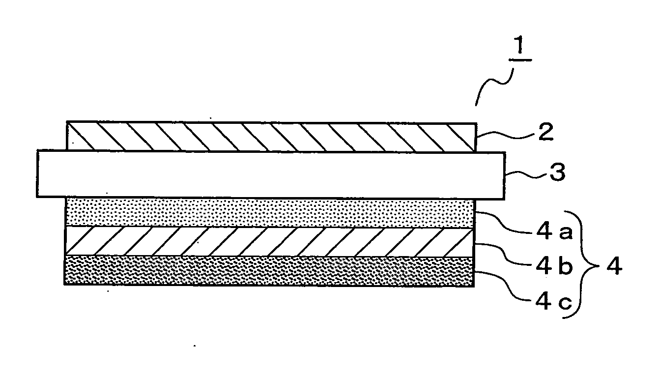
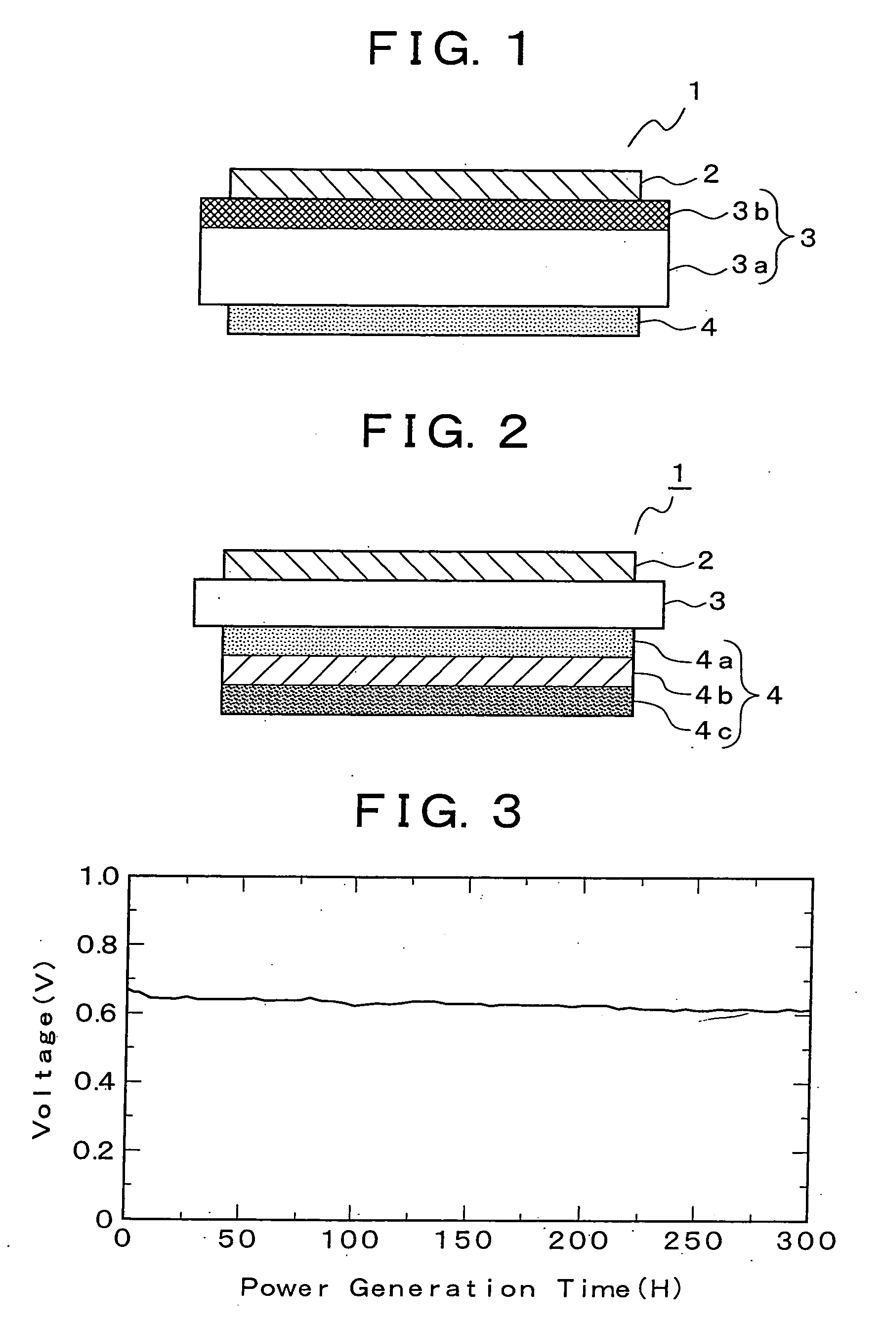
[0048] With reference to FIG. 2, the material for the air electrode layer 2 was Sm0.5Sr0.5Co0.3; the material for the solid electrolyte layer 3 was La0.8Sr0.2Ga0.8Mg0.15Co0.05O3; the composition ratio of component materials in the fuel electrode layer 4a was such that Ni(0 vol %) / Ce0.8Sm0.2O2 (100 vol %); the composition ratio of component materials in the fuel electrode layer 4b was such that Ni(10 vol %) / Ce0.8Sm0.2O2 (90 vol %); the composition ratio of component materials in the fuel electrode layer 4c was such that Ni(40 vol %) / Ce0.8Sm0.2O2 (60 vol %); and thus a power cell was formed and the obtained electric power generation property is shown in FIG. 3.
Login to View More PUM
 Abstract
A solid oxide fuel cell provided with a power cell (1) in which a fuel electrode layer (4) is arranged on one surface of a solid electrolyte layer (3) and an air electrode layer (2) is arranged on the other surface thereof, wherein the solid electrolyte layer (3) has a two layer structure including a first electrolyte layer (3a) made of a ceria based oxide material and a second electrolyte layer (3b) made of a lanthanum gallate based oxide material, and the second electrolyte layer is formed on the side of the air electrode layer. It is preferable that the first electrolyte layer is formed thinner than the second electrolyte layer. According to such a configuration, there can be provided a solid oxide fuel cell comprising an inexpensive solid electrolyte layer which reduces the contact resistances in the interfaces between the solid electrolyte layer and the respective electrode layers, and thereby improves the generation efficiency. Additionally, by adopting a configuration in which the composition ratio of component materials in the fuel electrode layer (4) is graded along the thickness thereof, there can be provided a solid oxide fuel cell in which the generation characteristics of the power cell are improved and the durability of the solid oxide fuel cell is improved. Preferably, the material composition for the fuel electrode layer (4) is a mixture of Ni and CeSmO2, wherein the composition ratio of component materials is graded along the thickness thereof in such a way that the quantity of Ni is made less than the quantity of CeSmO2 near the boundary interface with said solid electrolyte layer, and the mixing ratio of Ni is gradually increased with an increasing distance away from the interface.
Description
TECHNICAL FIELD [0001] The present invention relates to a solid oxide fuel cell which is provided with a power cell formed by arranging a fuel electrode layer on one side of a solid electrolyte layer and an air electrode layer on the other side of the solid electrolyte layer. More specifically, the present invention relates to a solid oxide fuel cell provided with a solid electrolyte layer improving the electric power generation performance of the electric power generation cell, or provided with a fuel electrode layer improving the durability of the fuel cell. BACKGROUND ART [0002] The development of a solid oxide fuel cell, having a layered structure in which a solid electrolyte layer made of an oxide ion conductor is sandwiched between an air electrode layer (oxidant electrode layer) and a fuel electrode layer, is progressing as a third-generation fuel cell for use in electric power generation. In a solid oxide fuel cell, oxygen (air) is supplied to the air electrode section and a...
Claims
Login to View More Application Information
Patent Timeline
 IPC IPC(8): H01M4/86H01M4/88H01M8/12
CPCH01M4/8621H01M4/8642H01M4/8885H01M4/9025H01M4/9066H01M8/1246H01M8/126Y02E60/525Y02P70/56Y02E60/50Y02P70/50
Inventor HOSHINO, KOJIHOSOI, KEIYAMADA, TAKASHIAKIKUSA, JUN
Owner MITSUBISHI MATERIALS CORP