Float valve assembly for battery

a technology of float valve and battery, which is applied in the direction of cell components, cell component details, secondary cell servicing/maintenance, etc., can solve the problems of prone to stick or jam, mechanism that links the float to the valve, and loss of water from the electrolyte solution

Active Publication Date: 2005-10-06
PHILADELPHIA SCI +1
View PDF53 Cites 13 Cited by
  • Summary
  • Abstract
  • Description
  • Claims
  • Application Information

AI Technical Summary

Benefits of technology

[0012] A flash arrester may be in fluid communication with the vent duct. The flash arrester comprises a porous medium positioned within a chamber located between the vent duct and an outlet. The medium is in spaced relation to a cover enclosing the chamber. The hydrogen and oxygen gases pass from the cell through the medium into the space between the medium and the cover before exiting to the ambient through the outlet. The pores of the medium are sized to quench hydrogen-oxygen combustion and stop it from flashing into and igniting the cell. The space between the medium and the cover allows a controlled mini-explosion to extinguish any flame which could burn on the surface of the medium, melt it and then ignite the cell.

Problems solved by technology

The electrolysis causes a loss of water from the electrolyte solution, and as a result, such batteries require periodic replenishment of the lost water.
One weakness of float actuated valves currently in use lies in the mechanism that links the float to the valve.
This mechanism typically has several moving parts and is prone to stick or jam over time because it becomes fouled with a sticky tar-like residue formed by sulfuric acid reacting with mineral oil which leaches out of the polyethylene material forming the walls of each cell.
Actual field experience in Europe and the U.S. indicates that present float valves tend to fail in less than 18 months in high temperature or heavy duty service.
Another weakness of float valves is their lack of resistance to progressive hydrogen-oxygen explosions traveling between cells.
Unfortunately, the water does not always remain within the trap.
Yet another problem associated with current float actuated valves is their lack of a flash arrester for hydrogen gas that vents from the cell to the ambient.
Such flash arresters would be effective at preventing a hydrogen-oxygen explosion, but are often not used because they tend to restrict gas flow from the cells which causes a back pressure to develop within the cells.

Method used


Image

  • Float valve assembly for battery
  • Float valve assembly for battery
  • Float valve assembly for battery

Examples


Embodiment Construction

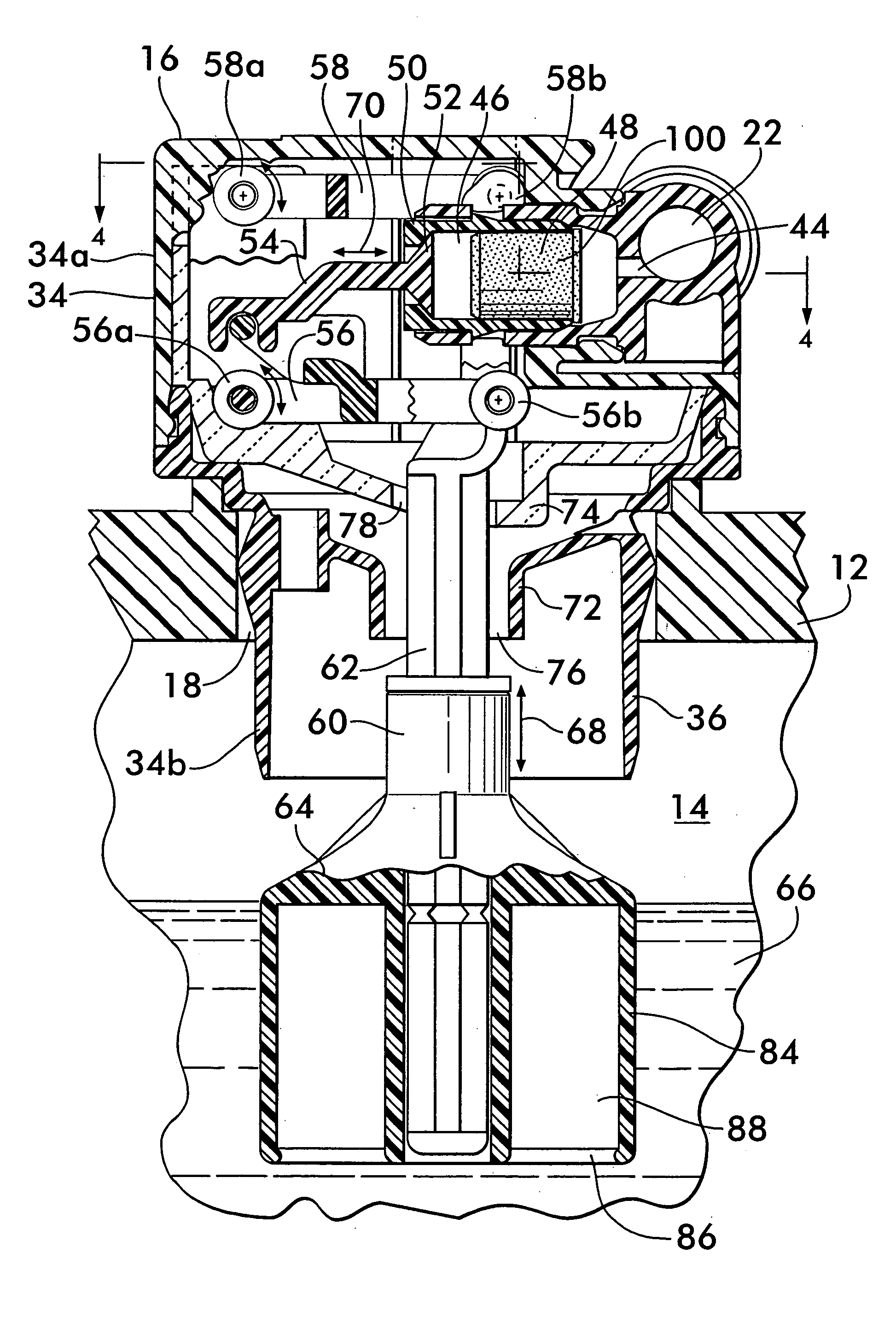
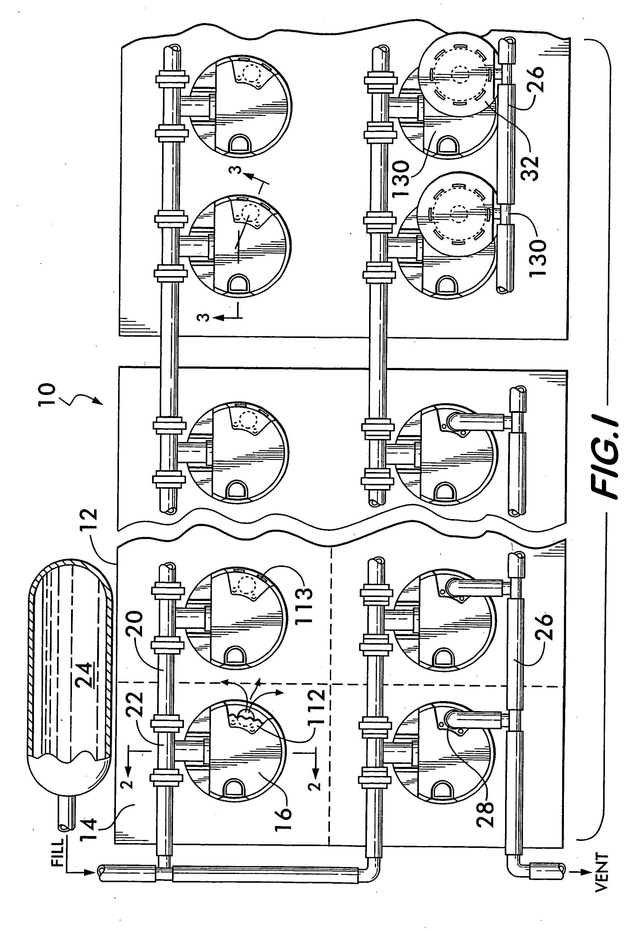
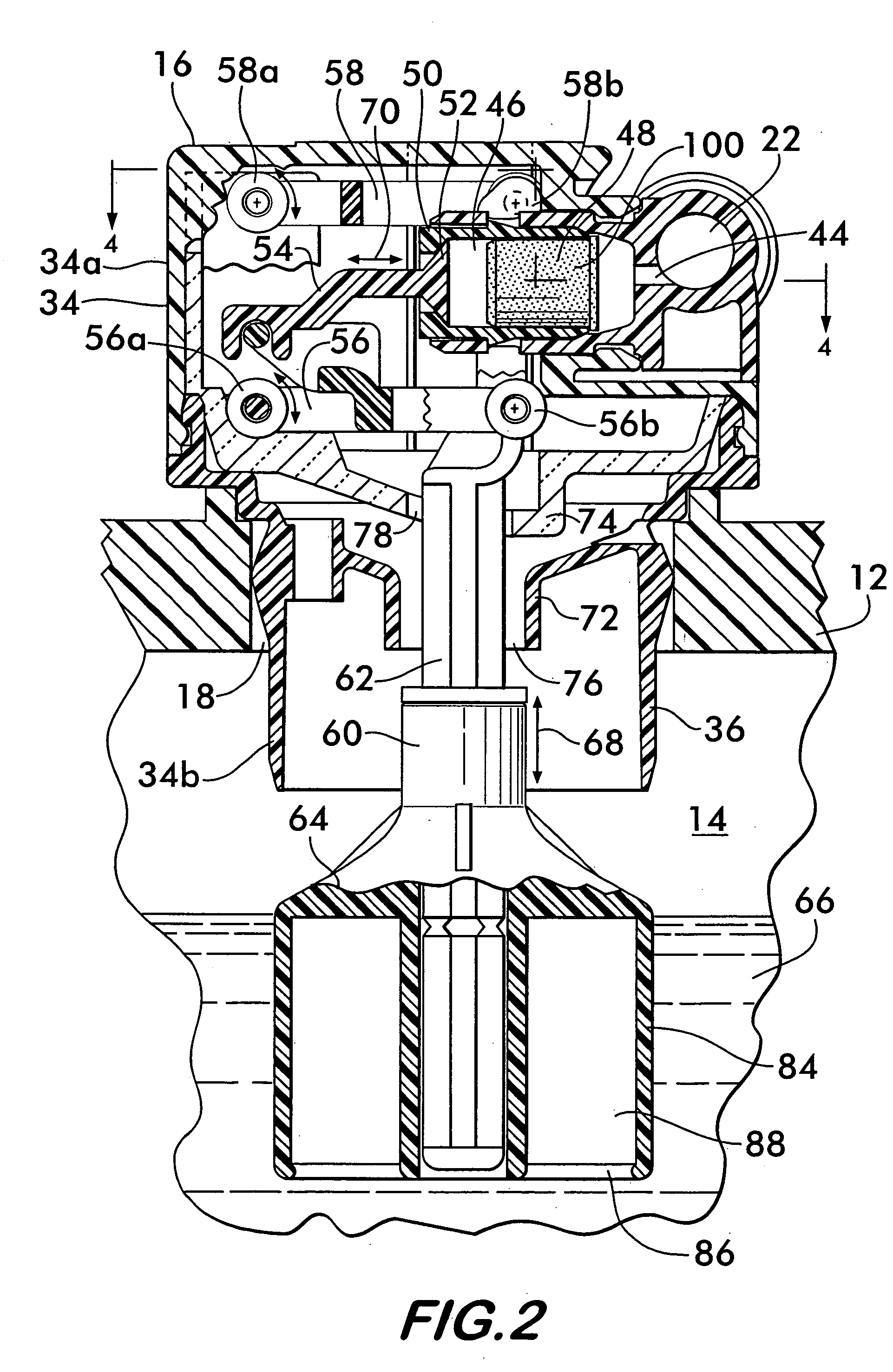
[0020]FIG. 1 shows an aqueous electrolyte battery 10 comprising a casing 12 divided into a plurality of cells 14, each cell having its own float valve assembly 16 sealingly engaged with a vent opening 18 in the cell (see also FIG. 2). Float valves 16 are connected in series to one another by a fluid conduit 20 that engages tee fittings 22 on each float valve. The conduit 20 is connectable to a water source 24 which provides water to replenish electrolyte lost from the cells during charging. During water replenishment, each float valve 16 controls the flow of water to its associated cell as described below. The float valves may also be connected to a gas conduit 26 in fluid communication with a gas discharge outlet 28 on each float valve. The gas discharge outlet allows oxygen and hydrogen gas, generated by electrolysis during charging, to vent from the cells. The gas conduit 26 conducts the gas away to be discharged to the ambient remotely from the cells 14. A flash arrester 32, des...


PUM

PropertyMeasurementUnit
movementaaaaaaaaaa
flexibleaaaaaaaaaa
sizesaaaaaaaaaa

Abstract

A float actuated valve assembly for battery electrolyte replenishment is disclosed. A housing engages an opening in a battery cell. An inlet in the housing is connetable to a water source. A valve in the housing controls the water flow to the cell. The valve is connected by a link to a four bar mechanism that is attached to a float. The float is buoyantly supported and rises and falls in response to the electrolyte level within the cell opening and closing the valve to admit or halt the flow of water to the cell. A baffle prevent fouling of the mechanism by splashing electrolyte. A flash arrester is positioned between the valve and the inlet to quench hydrogen-oxygen explosions between cells. The float is adjustable for different sized cells. A side viewable electrolyte level indicator is provided in the housing. Flash arresters for venting gas are also mounted.

Description

FIELD OF THE INVENTION [0001] The invention concerns float actuated valves for controlling the flow of water to battery cells for replenishment of aqueous electrolyte. BACKGROUND OF THE INVENTION [0002] Float actuated valves are used to control the flow of water into a cell of a battery for replenishing the aqueous electrolyte that is lost during battery charging. Such batteries typically comprise a casing containing a number of individual cells each holding an electrolyte solution in which plates are immersed. Examples of batteries having an aqueous electrolyte include nickel-cadmium batteries or lead-acid type batteries. Oxygen and hydrogen gases are produced during charging as a result of electrolysis of the water. The gases bubble up through the electrolyte, cause splashing of the electrolyte at its free surface within the cells, and accumulate in a gas space above the plates and the electrolyte. The electrolysis causes a loss of water from the electrolyte solution, and as a res...

Claims


Application Information

Patent Timeline
Patent Type & Authority Applications(United States)
IPC IPC(8): A62C4/02F16K17/38F16K24/04F16K31/18F16K31/26H01M10/42H01M50/636
CPCF16K24/048F16K31/26F16K31/265H01M2/1247H01M2/127H01M2/36H01M2/362H01M2/368H01M10/4214Y10T137/7358Y02E60/10H01M50/383H01M50/394H01M50/636
Inventor JONES, WILLIAM E. M.ALDEN, TREVOR
Owner PHILADELPHIA SCI
Why Eureka
Try Eureka