RFID tire label

a tire label and tire technology, applied in the field of labels, can solve the problems of weak adhesive bonding, limited adhesion, and difficult to remove labels, and achieve the effects of easy removal in one piece, loss of tensile strength, and strong and more tear resistan

Active Publication Date: 2005-10-06
INTERMEC IP
View PDF15 Cites 37 Cited by
  • Summary
  • Abstract
  • Description
  • Claims
  • Application Information

AI Technical Summary

Benefits of technology

[0013] As label tags age they can become brittle, losing their tensile strength. Thus, prior art tire labels often tear when removed. In the present invention a polyester mesh face stock is stronger and more tear r

Problems solved by technology

Stiff label films tend to lift from the tire surface and offer limited adhesion due to non-conforming solid films.
Prior art tire labels have weak adhesive bonds and label staining occurs due t

Method used


Image

  • RFID tire label
  • RFID tire label
  • RFID tire label

Examples


Embodiment Construction

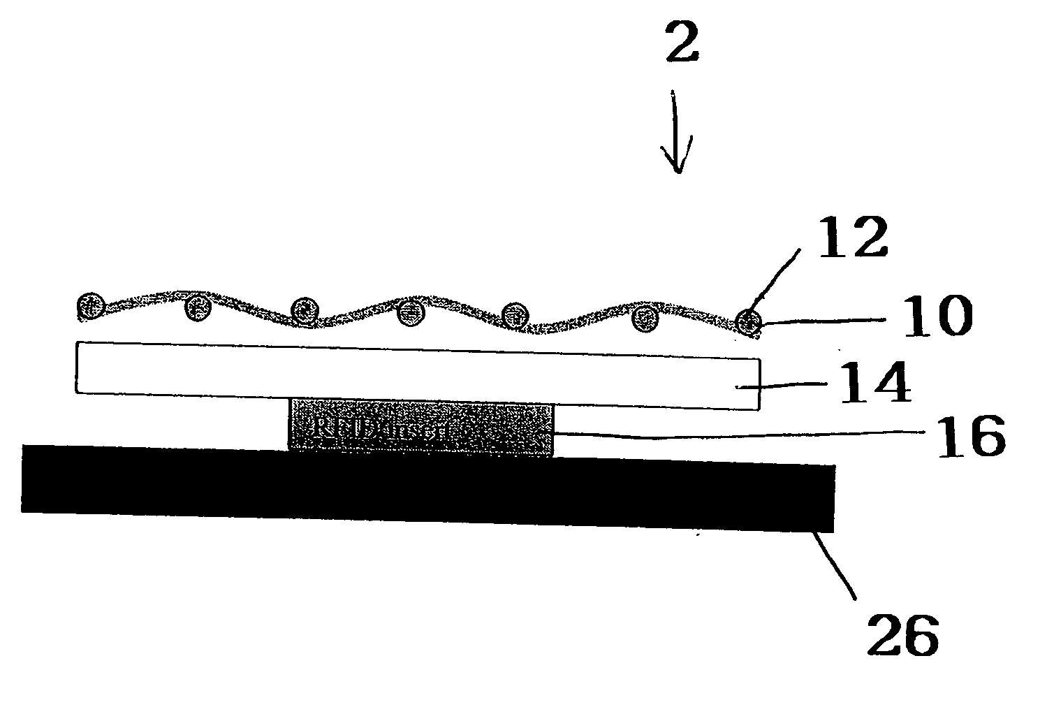
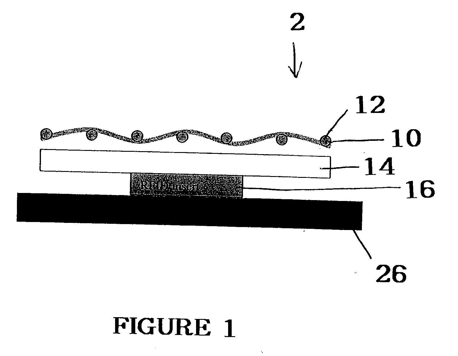
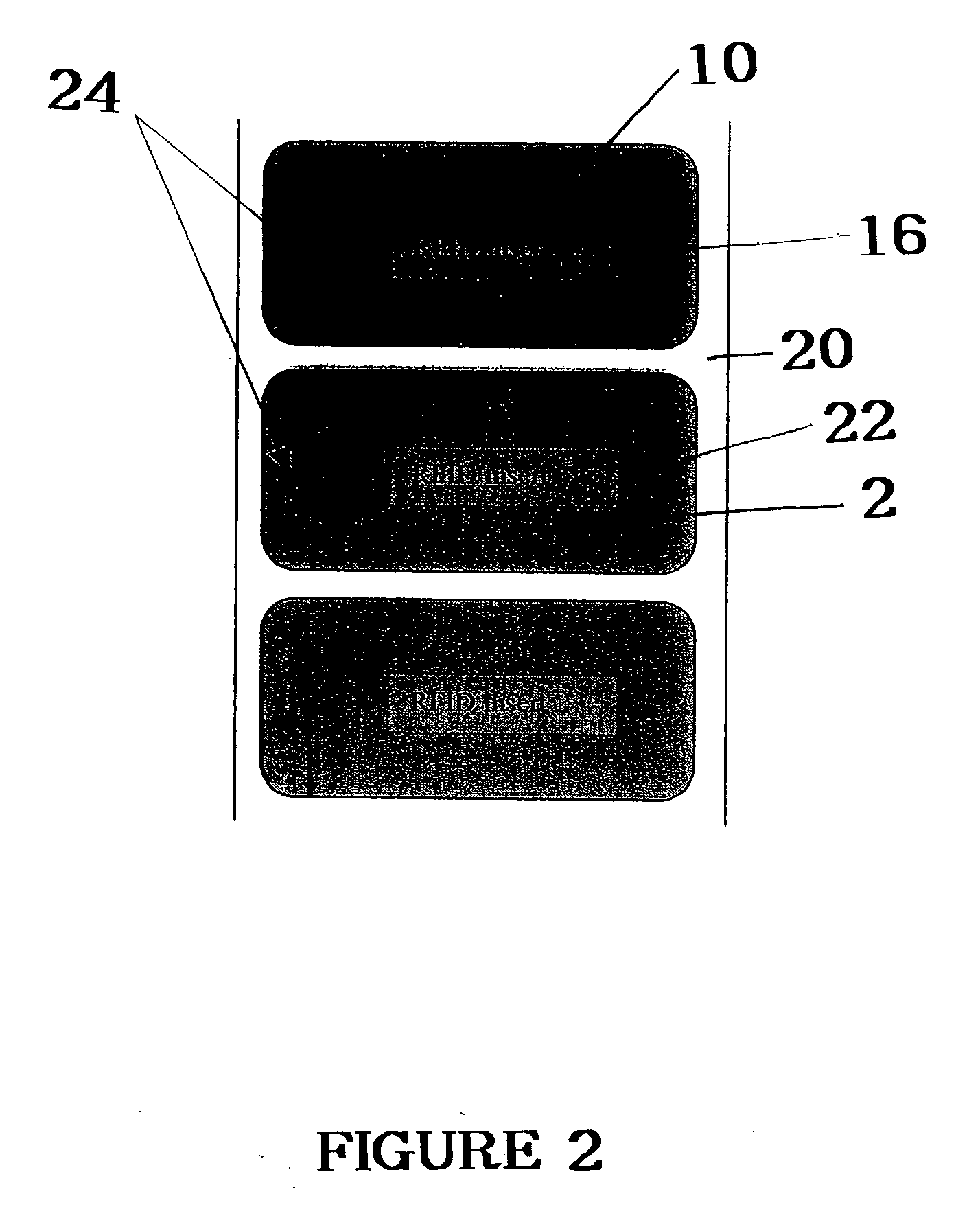
[0019] Radio frequency transponders (RFID tags) generally include an antenna and integrated memory circuit with read / write capability used to store digital information, such as an electrically erasable programmable read only memory (EEPROM) or similar electronic device. Active RFID tags include their own radio transceiver and power source, for example a battery, and are generally sealed within a molded plastic housing. Passive RFID tags are energized to transmit and receive data by an electromagnetic field and do not include a radio transceiver or power source. As a result, they are small and inexpensive with limited range, resolution and data storage capacity. Passive RFID tag inserts used in the Automatic Identification Industry are typically laminated or inserted into a paper or plastic label stock backed with pressure sensitive adhesive for applying the printed label to a carton, pallet, airline baggage, parcel or other article to be tracked. These labels are commonly referred t...


PUM

PropertyMeasurementUnit
Lengthaaaaaaaaaa
Diameteraaaaaaaaaa
Diameteraaaaaaaaaa

Abstract

A tire label that is adapted to adhere to the surface of an irregular surface. The inventive tire label uses a label stock made of an openwork fabric that is a mesh, woven or knit. Optionally, a cap can be used on the label. Preferably, the label has an RFID chip.

Description

FIELD OF THE INVENTION [0001] The invention relates to labels. More specifically it relates to tire labels with RFID tags. [0002] The inventive RFID tire label is attached with a pressure sensitive adhesive to a tire (inside or outside) for use in automating the collection of information through the wheel mounting and final assembly processes. This RFID tire label design preferably uses an open mesh of woven polyester filaments for the face stock. BACKGROUND OF THE INVENTION [0003] Most tire labels whether they are tread labels or smart labels with RFID inserts are made from solid label films extruded from polymers such as polypropylene, polyethylene, polyvinyl chloride (vinyl), polyolefins and copolymer blends. The problem with these solid films is they can be stiff and non-conformable. Continuous exposure to ultraviolet radiation (sunlight) and high / low temperature extremes (thermal cycling) breaks down the film, resulting in loss of tensile strength, cracking, crazing, staining, ...

Claims


Application Information

Patent Timeline
IPC IPC(8): B32B7/12G06K19/077G09F3/10
CPCB32B7/12Y10T428/2848G06K19/07764G09F3/10Y10T442/2746Y10T428/2843Y10T428/14B32B5/028B32B5/024B32B5/026B32B2519/02Y10T428/28Y10T442/2738Y10T442/2754G06K19/07749
Inventor CONWELL, KEVINROGERS, TOM
Owner INTERMEC IP
Why Eureka
Try Eureka