Apparatus for molding and assembling containers with stoppers and filling same

a technology for containers and containers, applied in the direction of packaging goods, liquid handling, closures using stoppers, etc., can solve the problems of defective filling of dispensers or containers, time-consuming filling process, and high cost of processes and equipmen

Inactive Publication Date: 2005-10-13
MEDINSTILL DEV
View PDF66 Cites 84 Cited by
  • Summary
  • Abstract
  • Description
  • Claims
  • Application Information

AI Technical Summary

Benefits of technology

[0012] One advantage of the present invention is that the sterile stoppers and container bodies are assembled, preferably under sterile laminar flow, either within the molding machine(s) or promptly upon discharge from the molding machine(s), while the parts are still hot and sterile. Thus, there is no need to gamma irradiate or otherwise sterilize at least the interiors of the containers after assembly.

Problems solved by technology

One of the drawbacks associated with such prior art dispensers or containers, and processes and equipment for filling such dispensers or containers, is that the filling process is time consuming, and the processes and equipment are expensive.
Further, the relatively complex nature of the filling processes and equipment can lead to more defectively filled dispensers or containers than otherwise desired.
In many cases, there are complex assembly machines for assembling the dispensers or containers that are located within the aseptic area of the filling machine that must be maintained sterile.
This type of machinery can be a significant source of unwanted particles.
In closed barrier systems, convection flow is inevitable and thus laminar flow, or substantially laminar flow, cannot be achieved.
When operation of an isolator is stopped, a media fill test may have to be performed which can last for several, if not many days, and can lead to repeated interruptions and significant reductions in production output for the pharmaceutical, nutritional or other product manufacturer that is using the equipment.
In order to address such production issues, government-imposed regulations are becoming increasingly sophisticated and are further increasing the cost of already-expensive isolators and like filling equipment.
On the other hand, governmental price controls and marketplace competition for pharmaceuticals and vaccines, including, for example, preventative medicines, and other aseptically filled products, such as liquid nutrition products, discourage such major financial investments.
One of the drawbacks of gamma sterilization is that it can damage or otherwise negatively effect the parts to be sterilized, such as by discoloring parts formed of plastic and other gamma-sensitive materials.
In addition, if used to terminally sterilize filled containers, gamma radiation can damage the product stored within the container.
Accordingly, gamma sterilization has limited applicability, and further, is not always a desirable form of sterilization for many types of products with which it is used.

Method used


Image

  • Apparatus for molding and assembling containers with stoppers and filling same
  • Apparatus for molding and assembling containers with stoppers and filling same
  • Apparatus for molding and assembling containers with stoppers and filling same

Examples


Embodiment Construction

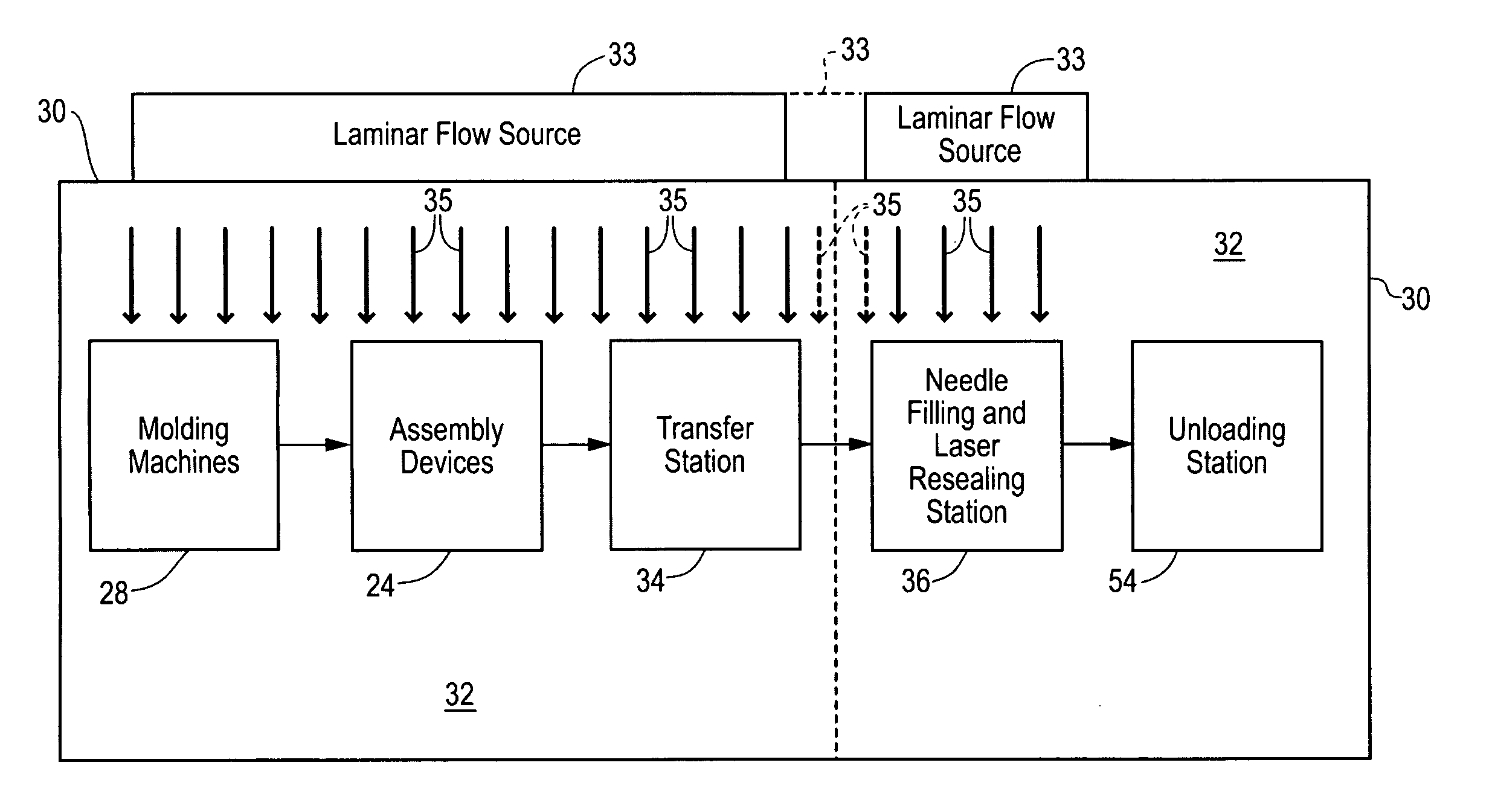
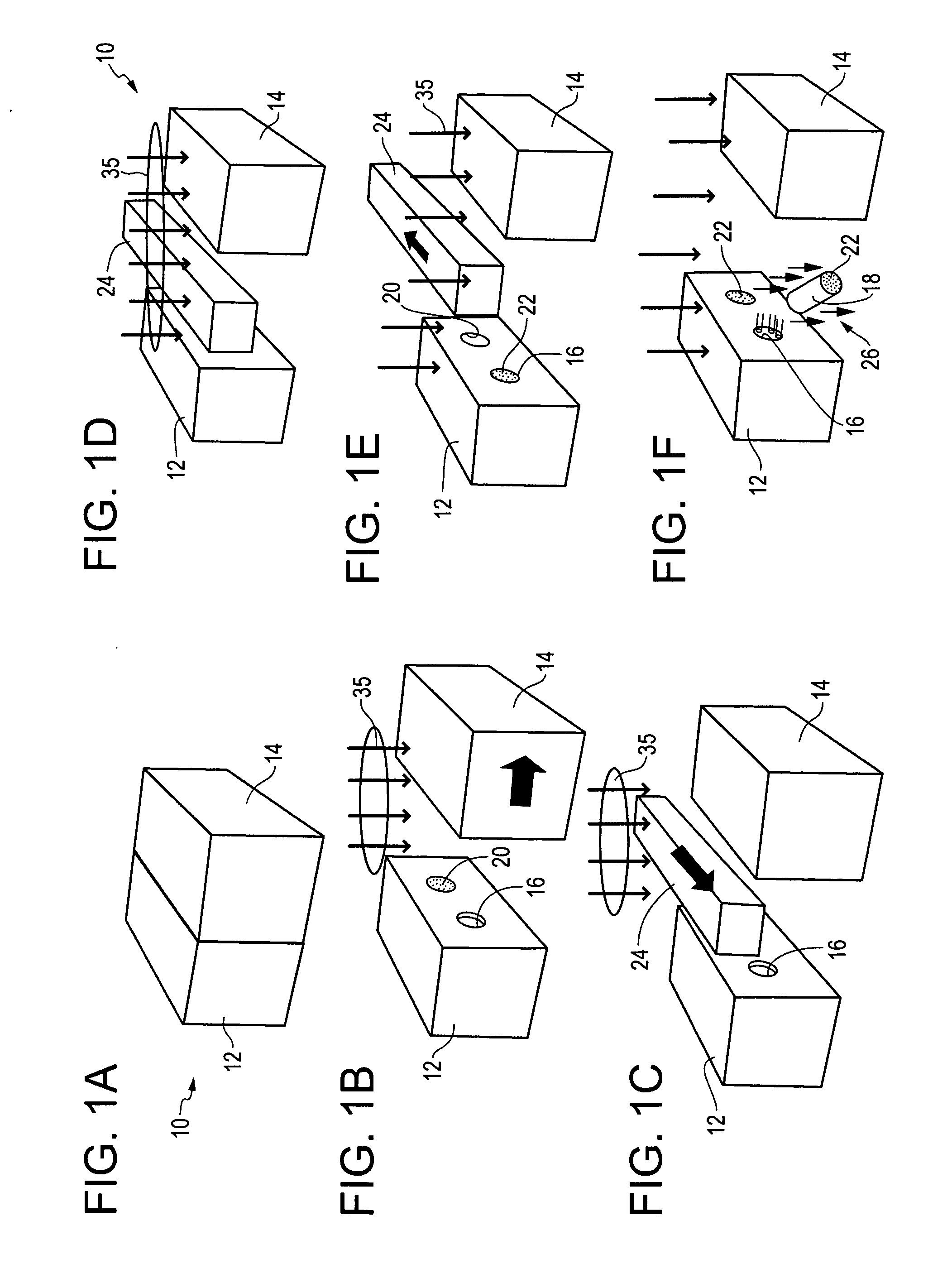
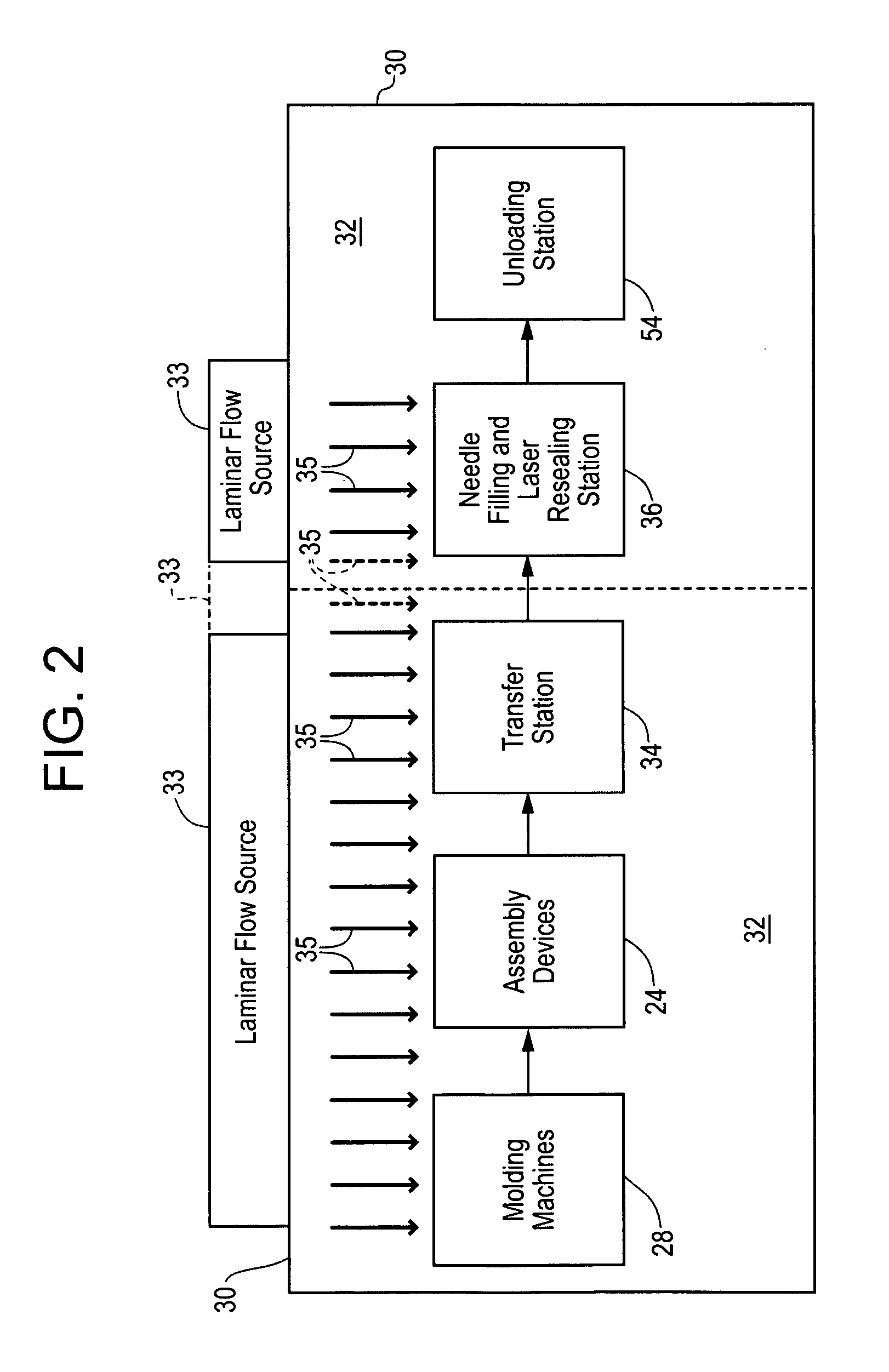
[0017] In FIGS. 1A through 1F, an apparatus embodying the present invention is indicated generally by the reference numeral 10. The apparatus 10 comprises a first mold or die 12, and a second mold or die 14. The first and second molds 12 and 14, respectively, are movable relative to one another in a manner known to those of ordinary skill in the pertinent art between a closed position for molding the container parts therein, and an open position for releasing the molded container parts therefrom. Although both molds 12 and 14 are shown as being movable relative to each other, if desired or otherwise required, only one of the molds may be movable relative to the other. In addition, each mold or die may comprise any desired number of parts, including, for example, moving parts, as may be desired or otherwise required. The first and second molds 12 and 14 cooperate to define a first mold cavity 16 that is shaped to form the container body 18, and a second mold cavity 20 that is shaped ...


PUM

PropertyMeasurementUnit
temperaturesaaaaaaaaaa
perimeteraaaaaaaaaa

Abstract

A stopper and container body are molded in the same molding machine. An assembly device, such as a pick and place robot, transfers the stopper from one mold cavity into the opening in the container body located within another mold cavity, or vice versa, to assemble the stopper and container body. Then, the assembled container body and stopper are removed from the molding machine and transported to a needle filling and laser resealing station for filling and laser resealing. A laminar flow source directs a substantially laminar flow of air or sterile gas over the mold surfaces, stoppers and container bodies, and assembly device, to prevent contamination during assembly.

Description

CROSS-REFERENCE TO RELATED APPLICATIONS [0001] This patent application claims the benefit of U.S. Provisional Patent Application Ser. No. 60 / 551,565, filed Mar. 8, 2004, entitled “Apparatus And Method For Molding And Assembling Containers With Stoppers And Filling Same”, which is hereby expressly incorporated by reference as part of the present disclosure. This patent application also includes subject matter related to that disclosed in the following patent applications: U.S. Patent Application entitled “Method For Molding And Assembling Containers With Stoppers And Filling Same”, filed on even date herewith under Attorney Docket No. INSC-205.2; U.S. patent application Ser. No. 10 / 766,172 filed Jan. 28, 2004, entitled “Medicament Vial Having A Heat-Sealable Cap, And Apparatus and Method For Filling The Vial”, which is a continuation-in-part of similarly titled U.S. patent application Ser. No. 10 / 694,364, filed Oct. 27, 2003, now U.S. Pat. No. 6,805,170, which is a continuation of si...

Claims


Application Information

Patent Timeline
Patent Type & Authority Applications(United States)
IPC IPC(8): B65B31/02B65B3/00B65B7/28B65B3/02B65B61/00
CPCB65B3/003B65B3/022B65B31/027
Inventor PY, DANIEL
Owner MEDINSTILL DEV
Why Eureka
Try Eureka