Method of producing magnetic particles and reaction method using microreactor and microreactor

a technology of microreactor and reaction method, which is applied in the direction of magnetic materials for record carriers, magnetic bodies, transportation and packaging, etc., can solve the problems of line instability, inability to produce minute alloy particles excellent in monodispersibility and excellent in ease in transformation, and inability to use conventional microreactors for the reaction where by-product gas is not available, etc., to achieve excellent in monodispersibility, excellent in ease in transformation, and reduce noise

Active Publication Date: 2005-10-13
FUJIFILM CORP +1
View PDF4 Cites 33 Cited by
  • Summary
  • Abstract
  • Description
  • Claims
  • Application Information

AI Technical Summary

Benefits of technology

[0010] However, in the preparation of alloy particles by a conventional mixing reactor, tank 2 has a dead space and stirring of liquid becomes uneven, and particle growth of the prepared alloy particles occurs due to partial circulation in the tank 2, and there is a defe

Problems solved by technology

However, in the preparation of alloy particles by a conventional mixing reactor, tank 2 has a dead space and stirring of liquid becomes uneven, and particle growth of the prepared alloy particles occurs due to partial circulation in the tank 2, and there is a defect that minute alloy particles excellent in monodispersibility and excellent in ease in transformation cannot be produced.
In addition, although minute magnetic particles excellent in monodisoersibility can be produced by a microreactor, some reaction involves generation of by-product gas (e.g., hydrogen gas) depending on the kind of magnetic particles and there is a problem that the conventional microreactors cannot be used for the reaction where by-product gas is generated.
As a result, continuous line of processing of liquid

Method used


Image

  • Method of producing magnetic particles and reaction method using microreactor and microreactor
  • Method of producing magnetic particles and reaction method using microreactor and microreactor
  • Method of producing magnetic particles and reaction method using microreactor and microreactor

Examples


first embodiment

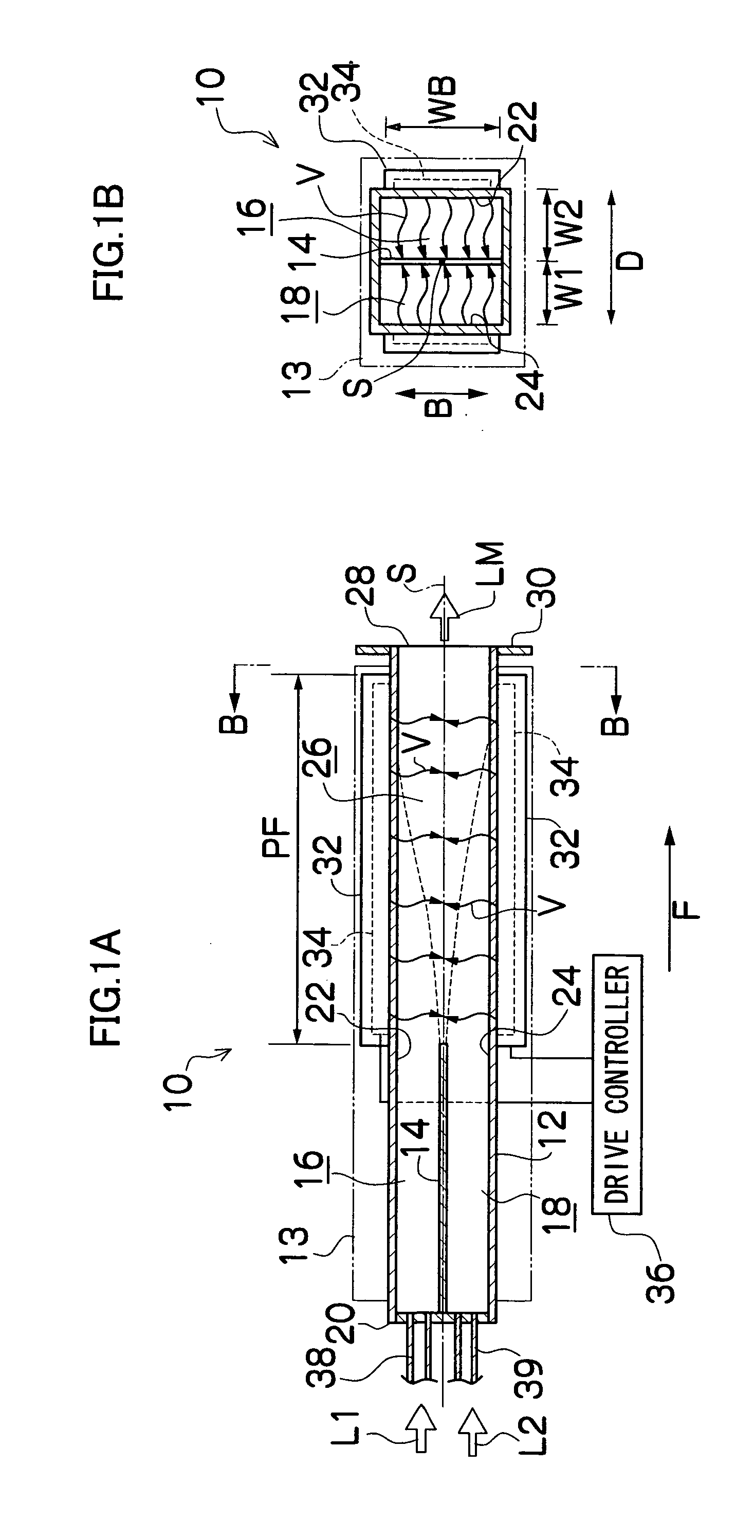
[0320]FIG. 9 is a perspective view illustrating the concept of the microreactor according to the first embodiment of the present invention, which is laminate flow microreactor 200. FIG. 10A is a top view of a microreactor main body (hereinafter referred to as main body 212) and FIG. 10B is a cross-sectional view taken on line a-a of FIG. 10A.

[0321] As shown in FIG. 9, laminate flow (substantially synonymous with parallel tube structure) microreactor 10 is mainly composed of a main body 212, liquid supply devices 216 and 216 which supply liquids L1 and L2 for liquid-liquid reaction to the main body 212 via liquid supply pipes 214 and 214, and a gas supplying device 220 which supplies gas G unreactive to liquids L1 and L2 for liquid-liquid reaction to the main body 212 via gas supply pipe 218. In this embodiment, explanation is made referring to an example of a liquid-liquid reaction involving generation of by-product gas using two liquids L1 and L2.

[0322] As shown in FIGS. 10A and ...

second embodiment

[0344] Next, an annular flow (synonymous with concentric multi-cylindrical structure) microreactor 260, which is the second embodiment of the microreactor of the present invention is described. Explanation is made referring to a liquid-liquid reaction using two liquids L1 and L2.

[0345] As shown in FIGS. 15A and 15B, the annular microreactor 260 is formed into a substantially columnar shape as a whole and provided with a circular pipe member 262 which constitutes the outer shell of the main body.

[0346] The straight line S in the figure indicates the axis of the reactor and the following description will be made referring to the direction along the axis S as the axial direction of the main body. At the tip of the circular pipe member 262 is opened a discharge opening 264 for a reaction product solution LM produced by the reaction of the liquids L1 and L2, and a ring-shaped flange part 266 is provided at the tip of the circular pipe member 262 to be extended toward the outer peripher...

third embodiment

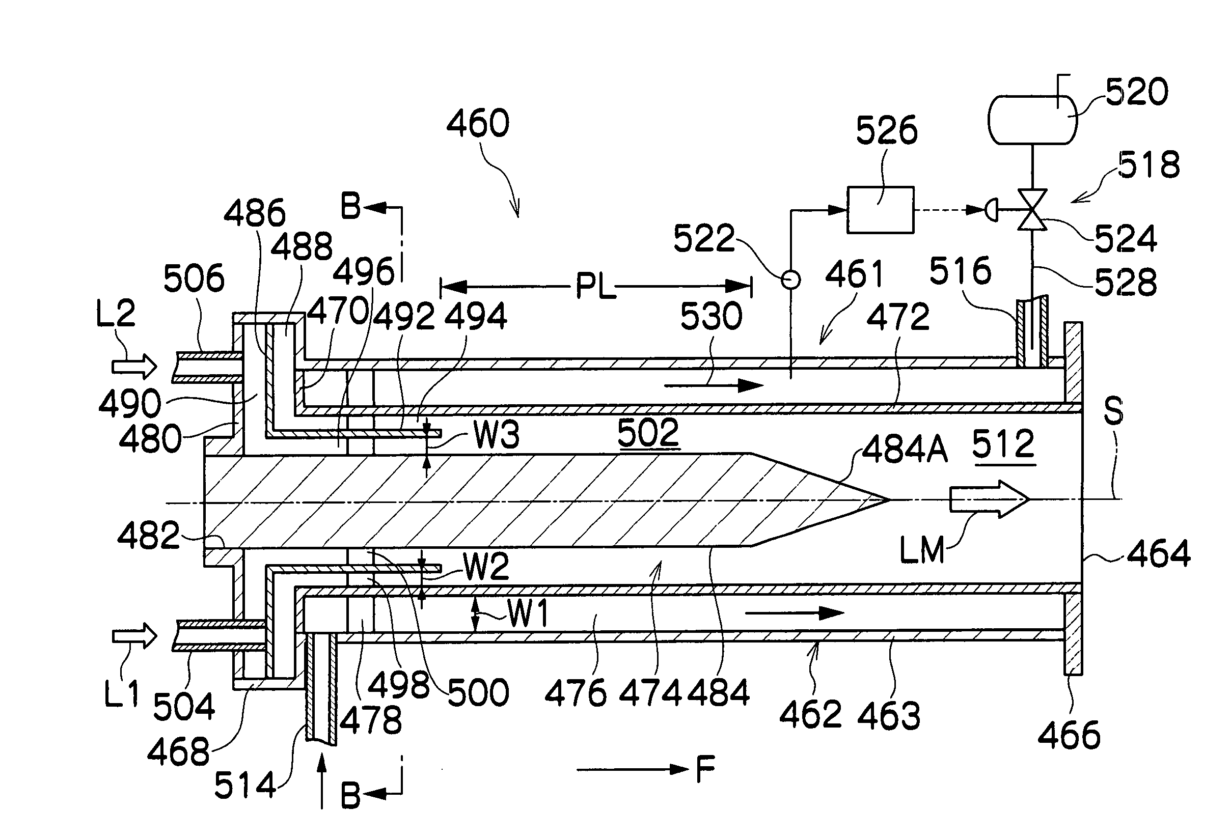
[0360]FIG. 18 is a perspective view illustrating the third embodiment of the present invention, which is a laminate flow microreactor 400. FIG. 19A is a top view, FIG. 19B is a cross-sectional view, and FIG. 19C is a bottom view of a microreactor main body (hereinafter referred to as main body 12).

[0361] As shown in FIG. 18 the laminate flow microreactor 400 is mainly composed of a main body 412 equipped with a gas permeation member 418, liquid supply devices 416 and 416 which supply liquids L1 and L2 for a liquid-liquid reaction involving generation of by-product gas to the main body 412 through liquid supply pipes 414 and 414 and a pressure control device 446 for improving the gas permeability of the gas permeation member 418. In this embodiment, explanation is made referring to an example of a liquid-liquid reaction using two liquids L1 and L2.

[0362] As shown in FIGS. 19A to 19C, the main body 412 is assembled by bonding a main body member 422 and lid member 424 by an adhesive ...


PUM

PropertyMeasurementUnit
Temperatureaaaaaaaaaa

Abstract

In a method of producing magnetic particles which includes the steps of preparing alloy particles capable of forming a CuAu or Cu3Au hard magnetic ordered alloy phase and of forming magnetic particles for forming CuAu or Cu3Au magnetic particles, a plurality of solutions L1 and L2 for preparing the alloy particles are passed in a thin-plate laminar flow and diffused in the direction perpendicular to the flow direction at the contact interface of the solutions L1 and L2 in a mixing channel by using a microreactor, whereby a uniform mixing reaction is conducted in a short time.

Description

BACKGROUND OF THE INVENTION [0001] 1. Field of the Invention [0002] The present invention relates to a method of producing magnetic particles by a microreactor and a reaction method using a microreactor suitable for producing magnetic particles involving generation of by-product gas, and a microreactor. [0003] 2. Description of the Related Art [0004] To increase magnetic recording density, it is important to make the particle size of magnetic particles contained in the magnetic layer small. For example, in the case of widely used magnetic recording media such as videotapes, computer tapes and diskettes, the smaller the noise, the smaller the particle size when the hard magnetic materials have the same mass. [0005] As a potential material of magnetic particles for improving the magnetic recording density, CuAu or Cu3Au hard magnetic ordered alloy has been attracting attention (e.g., Japanese Patent Application Laid-open No. 2003-6830, Japanese Patent Application Laid-open No. 2001-25...

Claims


Application Information

Patent Timeline
IPC IPC(8): B22F9/06B22F9/24G11B5/706H01F1/06H01F10/14
CPCB22F9/24B22F2998/00G11B5/70605H01F1/06H01F10/147B22F1/0085B22F1/0018H01F10/123B33Y80/00B22F1/054B22F1/142
Inventor SHIRAISHI, FUMIKOSUGIYAMA, SEIJIWAKI, KOUKICHIICHIKAWA, YASUNORIUEYAMA, TOMOHIDEHATTORI, YASUSHI
Owner FUJIFILM CORP
Why Eureka
Try Eureka