

Portable no-pump multi-fuel stove
a multi-fuel stove, portable technology, applied in the direction of gaseous heating fuel, stoves or ranges, combustion types, etc., can solve the problems of not being suitable for portable stoves, gas stoves with small energy output, and hardly used, and achieves small and light structure, easy separation, and easy exchange
- Summary
- Abstract
- Description
- Claims
- Application Information
AI Technical Summary
Benefits of technology
Problems solved by technology
Method used
Image

Examples
Embodiment Construction
[0041] Hereinafter, embodiments of the present invention will be described in detail with reference to the accompanying drawings.
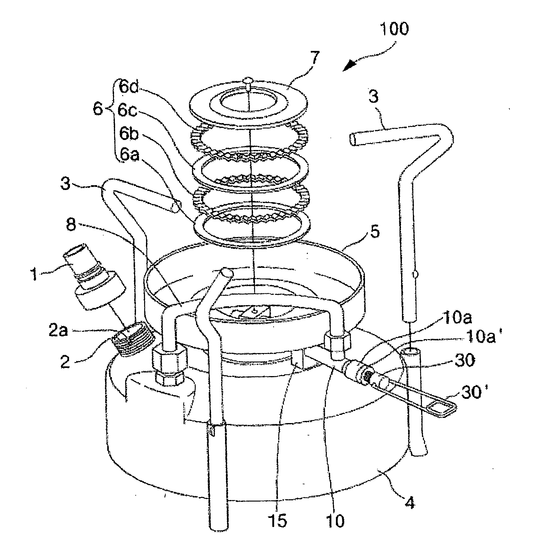
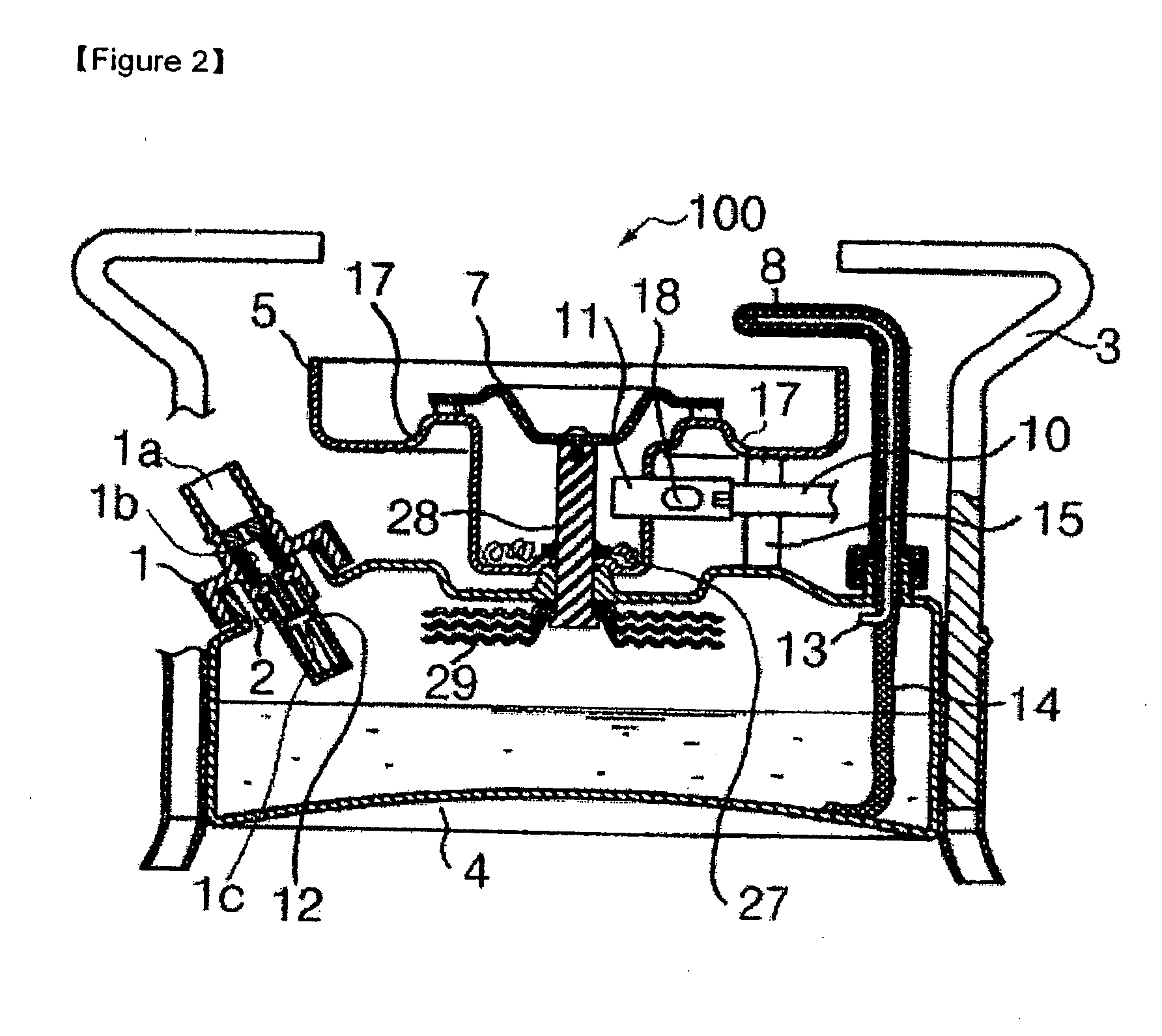
[0042]FIG. 1 is a perspective view showing a stove according to a preferred embodiment of the present invention, FIG. 2 is a longitudinal sectional view of FIG. 1, and FIG. 3 is a front view showing that a flame hole ring with a V-shaped groove and a flat flame hole ring are accumulatively assembled between a burner cap and a burner bowl of the stove shown in FIG. 1.
[0043] As shown in FIGS. 1 to 3, a portable stove 100 using both gasoline and gas according to a preferred embodiment of the present invention is configured so that a burner bowl 5 acting as a windscreen, a flame hole ring 6 where at least one ply of a flat flame hole ring and a flame hole ring with a V-shaped groove are accumulatively assembled, and a burner cap 7 are subsequently assembled to a central upper portion of a fuel tank 4 having a cylindrical shape with a fuel injection hole 2 to...
PUM
 Abstract
Description
Claims
Application Information