Landing gear method and apparatus for braking and maneuvering

a technology for landing gear and braking, applied in the direction of braking arrangements of aircraft, electric devices, transportation and packaging, etc., can solve the problems of reducing braking capacity, increasing the volume of carbon material needed to absorb the same amount, and introducing wear of associated disks, so as to reduce design costs, improve design efficiency, and add flexibility to the design of aircraft landing gear

Active Publication Date: 2005-10-13
DELOS AEROSPACE
View PDF68 Cites 106 Cited by
  • Summary
  • Abstract
  • Description
  • Claims
  • Application Information

AI Technical Summary

Benefits of technology

[0021] The wheel hub motor/generator may have mounted thereon a plurality of associated stator and rotor disk members which may be activated or deactivated individually, sequentially or in unison with the application of an electrical current or generation of electrical current in varying directions depending upon the need for motor and/or regenerative and/or motorized braking action. In one such case electromagnetic braking is applied by using associated rotor and stator disks as a generator and from which the output power from the stator is applied to another stator disk in such a manner as to increase the braking effect of the associated rotor of said other stator disk, thus accomplishing motorized braking action or motoring of a disk or disks which is acting as a generator within the same, or other wheel hub motor/generator, disk stack as that of the generating disk or disks.
[0022] The method of motor/generator electrical interconnections of different stator disk or disks within the same, or other wheel hub motor/generator, disk stack or motorized braking method as disclosed herein can be varied in numerous combinations of generator disk or disks and motor disk or disks within the present invention and is unique in the area of disk type axial flux motor/generators and offers flexibility in aircraft applications by allowing for the electrical and/or physical addition of disk or disks or removal of disk or disks based upon the aircraft landing weight and/or landing gear design needs. This electrical interconnection of disks in which any disk within the wheel hub motor/generator disk stack may act as a motor or as a generator or in any combination thereof is known as motorized braking method as proposed within the present invention, which adds flexibility to the design of aircraft landing gear. Incorporating the use of disk type axial flux motor/generators greatly reduces design cost due to this flexibility in motoring and braking of said motor/generat

Problems solved by technology

The current state of the art for providing braking systems for aircraft uses stators and rotors, which are forced into physical contact with each other thus generating friction heat that introduces wear of the associated disks and requires periodic maintenance to replace the worn parts.
The primary drawback of carbon disk brakes of the latest designs is that a greater volume of carbon material is needed to absorb the same amount of heat energy as that of steel disk brakes.
Another drawback of carbon disk brakes is the diminished braking capacity due t

Method used


Image

  • Landing gear method and apparatus for braking and maneuvering
  • Landing gear method and apparatus for braking and maneuvering
  • Landing gear method and apparatus for braking and maneuvering

Examples


Embodiment Construction

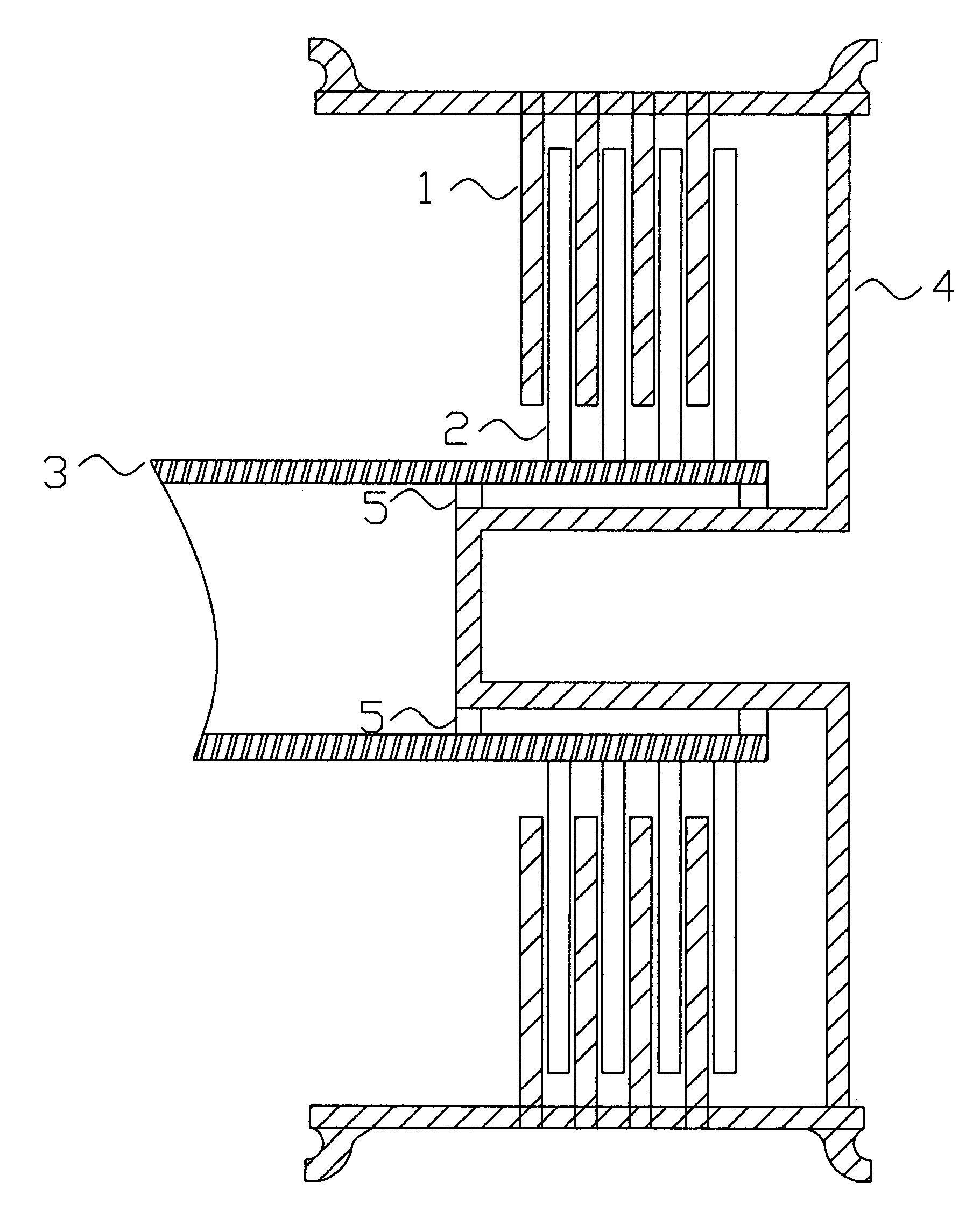
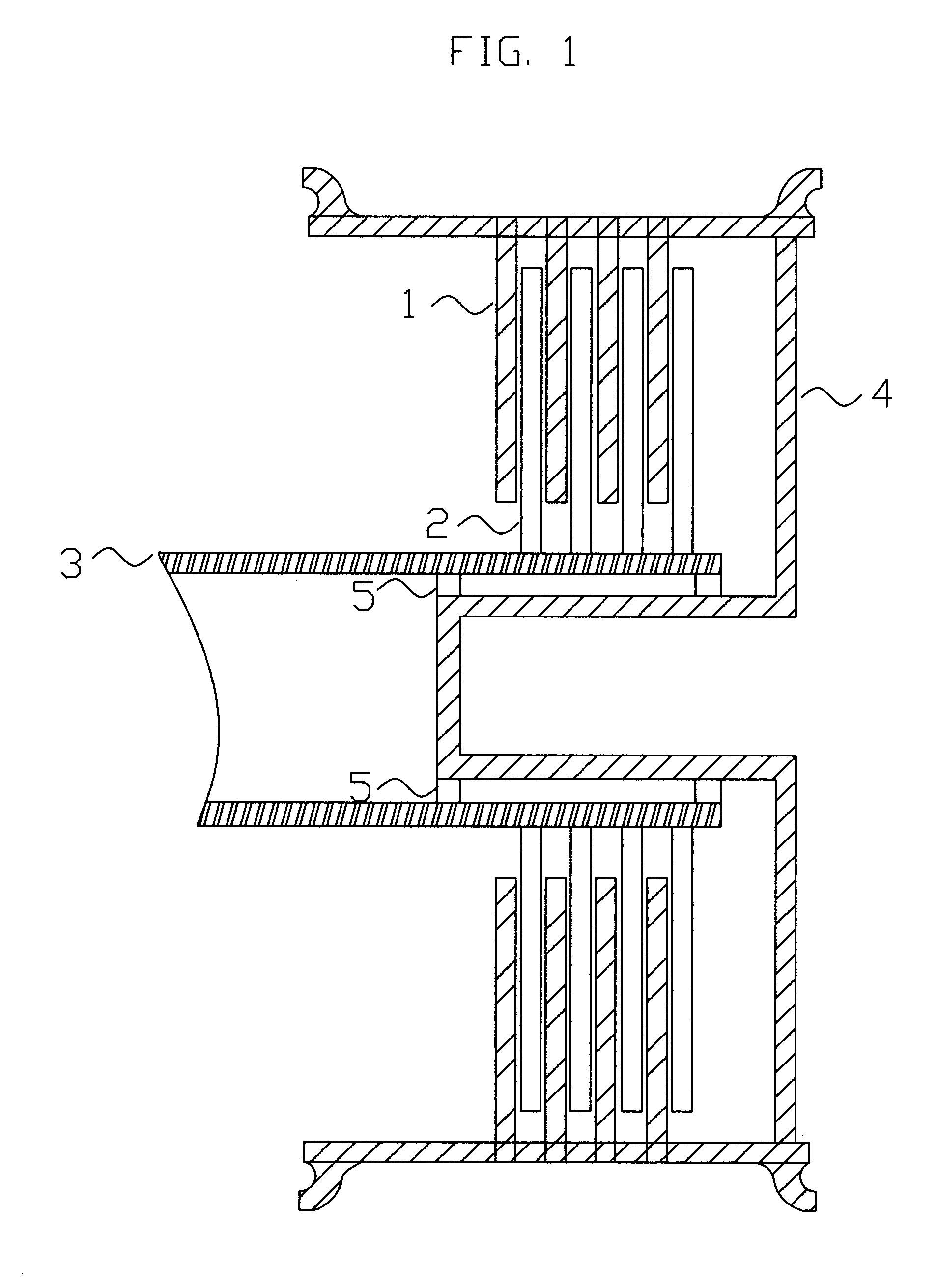
[0028]FIG. 1. Shows the cross sectional view of a possible disk stack axial flux type wheel hub motor / generator used to accomplish the needed electromagnetic braking and / or motoring of the landing gear wheels.

[0029] The rotors 1 are coupled to the wheel 4 and rotate with the wheel 4. The stator disks 2, which may be constructed of an electrically conductive material, are coupled to the shaft 3 and / or central torque tube, and are stationary with respect to the wheel in which said disks are electrically isolated from each other except through available electrical connections (not shown). The rotor disks 1, which may be constructed of an electrically conductive material or may be constructed of permanent magnets, are coupled to the wheel 4. The wheel 4 is supported by means of a bearing set 5, which may be comprised of inboard and outboard bearing sets or a sleeve, air, or magnetic type bearing.

[0030] In the preferred embodiment, prior to touchdown the wheel 4 is motorized by applyin...


PUM


Abstract

Aircraft landing gear comprised of a wheel hub motor/generator disks stack, includes alternating rotor and stator disks mounted with respect to the wheel support and wheel. The wheel hub motor/generator can provide motive force to the wheel when electrical power is applied, which may be applied prior to touch-down thus decreasing the difference in relative velocities of the tire radial velocity with that of the relative velocity of the runway thus greatly reducing the sliding friction wear of said tire. After touchdown the wheel hub motor/generator may be used as a generator thus applying a regenerative braking force and/or a motorized braking action to the wheel. The energy generated upon landing maybe dissipated through a resistor and/or stored for later use in providing a source for motive power to the aircraft wheels for the purpose of taxiing and ground maneuvers of said aircraft.

Description

BACKGROUND OF THE INVENTION [0001] 1. Field of the Invention [0002] The Invention relates to aircraft landing gear and, more specifically to an integrated wheel hub motor / generator, regenerative braking and / or motorized braking method for an aircraft landing gear system, which reduces wear of the braking system and the associated tires while improving stability of said aircraft and reducing the need for maintenance due to wear. [0003] 2. Related Art [0004] It is known in the field of aircraft wheel and brake assemblies to provide a non-rotatable wheel support, a wheel mounted to the wheel support for rotation, and a brake disk stack using friction braking to convert rotatory motion of said disks into friction heat energy which creates wear of said disks. Various brake actuation configurations and methods are known, as in U.S. Pat. Nos. 4,381,049, 4,432,440, 4,542,809, 4,567,967, 4,596,316, 4,865,162 and 6,615,958. [0005] The current state of the art for providing braking systems for...

Claims


Application Information

Patent Timeline
IPC IPC(8): B64C25/40B64C25/42
CPCB60L7/26B60L2220/44B60L2240/30B60L2250/24B64C25/50B64C25/42Y02T50/823B64C25/34B64C25/405Y02T50/80
Inventor SULLIVAN, STEVEN LEO
Owner DELOS AEROSPACE
Why Eureka
Try Eureka