Optical fiber communications method and system without a remote electrical power supply

Active Publication Date: 2005-10-13
NEXTG NETWORKS INC
View PDF8 Cites 224 Cited by
  • Summary
  • Abstract
  • Description
  • Claims
  • Application Information

AI Technical Summary

Benefits of technology

[0010] An object of the present invention is to provide a means of deploying remote antenna units for radio frequency signal transm

Problems solved by technology

There are drawbacks to both ways of providing remote electrical power.
Local electrical power supplies can be expensive or impractical to install, depending on the circumstances of the remote locations.
Composite cable (containing mixed fiber and copper) is not a preferred cable type within the cabling industry and also has a relatively short reach capability due to ohmic losses in the copper.
Furthermore, there are special situations, such as hazardous explosive environments and milit

Method used


Image

  • Optical fiber communications method and system without a remote electrical power supply
  • Optical fiber communications method and system without a remote electrical power supply
  • Optical fiber communications method and system without a remote electrical power supply

Examples


Embodiment Construction

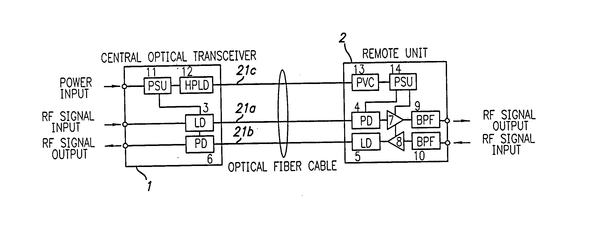
[0030] In the following description of preferred embodiments, reference is made to accompanying drawings which form a part hereof and in which is shown by way of illustration specific embodiments in which the invention may be practiced. It is to be understood that other embodiments may be utilized and structural changes may be made without departing from the scope of the preferred embodiments of the present invention.

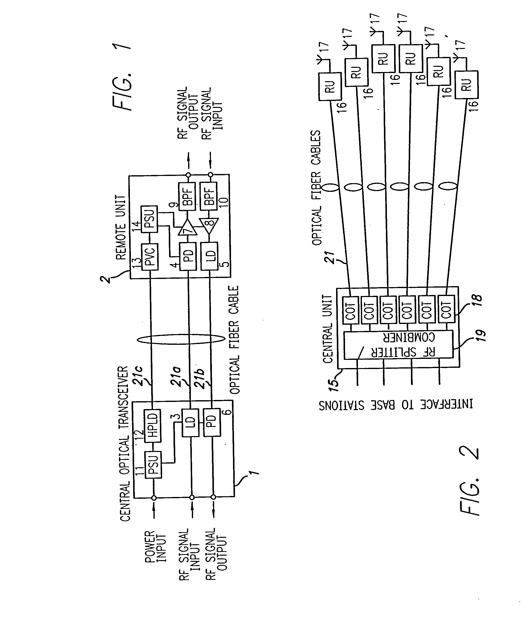
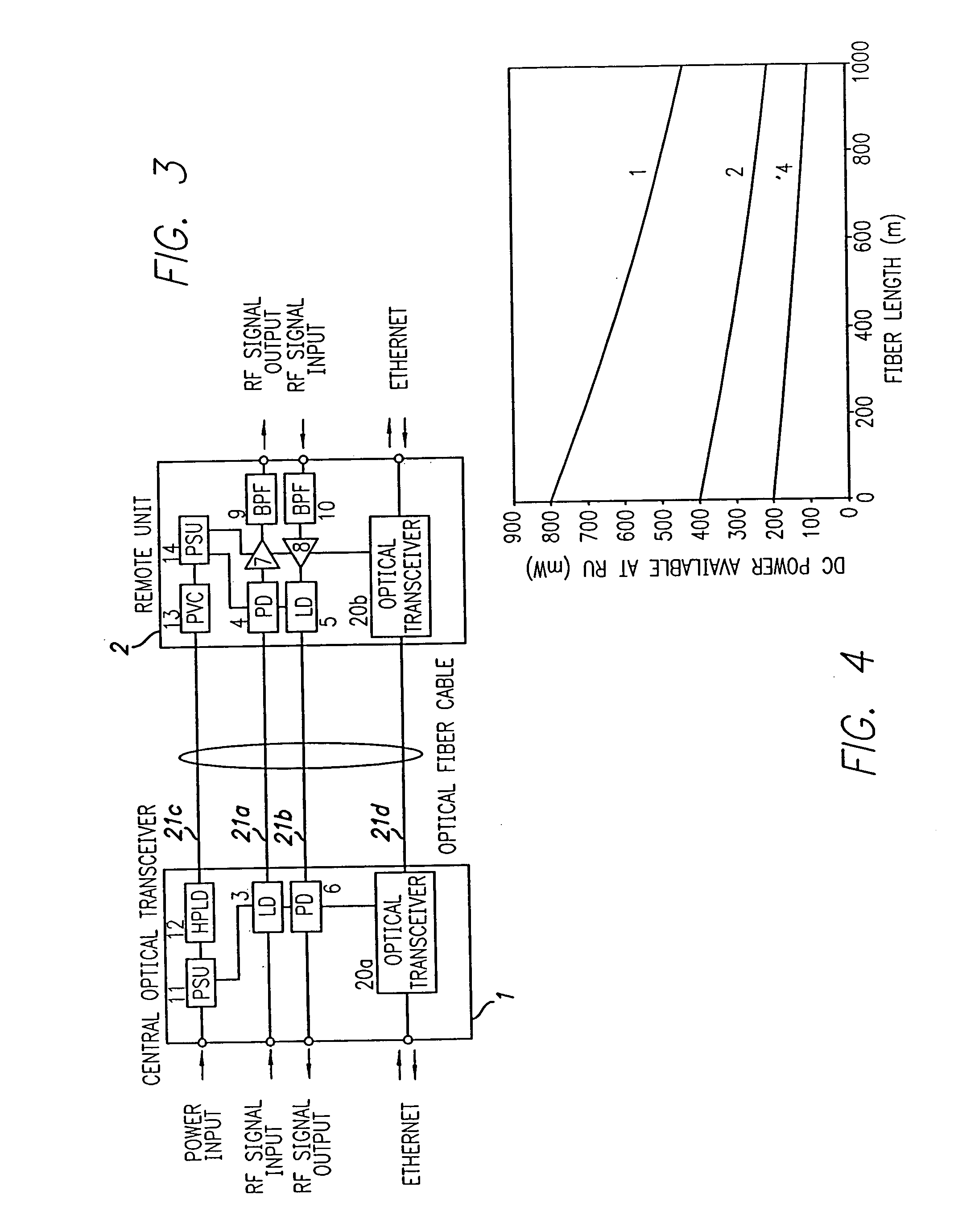
[0031]FIG. 1 illustrates an optical communications system of the present invention. A central optical transceiver (COT) 1 is connected to one or more remote units (RU) 2 via optical fiber cable. The forward optical fiber data path or link comprises a laser diode 3 in the COT and a photodiode 4 in the RU linked using an optical fiber 21a. The photodiode 4 converts optical data signals from the COT to radio frequency signals for transmission by an antenna (not illustrated in FIG. 1).

[0032] The reverse optical fiber data path or link comprises of a laser diode 5 in the R...


PUM


Abstract

The present invention allows remote antenna units for radio frequency signal transmission and receipt to operate without the requirement for remote electrical power supplies or for connecting cables that incorporate electrical conductors. According to an aspect of the present invention, an optical communications system employing radio frequency signals comprises a central unit; at least one remote unit having at least one optoelectronic transducer for converting optical data signals to radio frequency signals and converting radio signals to optical signals and at least one antenna to receive and send radio frequency signals; at least one optical fiber data link between the central unit and the remote unit for transmitting optical data signals therebetween; and at least one optical fiber power link between the central unit and the remote unit for providing electrical power at the remote unit.

Description

BACKGROUND OF THE INVENTION [0001] 1. Field of the Invention [0002] The present invention relates to optical fiber communications methods, systems and terminals for use in such systems and to cellular and radio distribution points. [0003] 2. Description of the Related Art [0004] The use of analog optical fiber transmission links to distribute cellular and other radio communications signals from a central location (where the radio base stations are situated) to one or more remote locations (where the antenna points are situated) is a well established technique commonly known as “radio over fiber.” Radio over fiber makes use of the broad bandwidth and low attenuation characteristics of optical fiber, which allows these systems to be deployed over very long spans for applications such as shopping malls and airports in the case of cellular radio. The remote antenna units in these systems comprise an optical transmitter (laser), an optical receiver (photodiode) and various electrical com...

Claims


Application Information

Patent Timeline
IPC IPC(8): H04B10/00H04B10/12H04W88/08
CPCH04B10/25753H04W88/085H04B10/806
Inventor WAKE, DAVIDWEBSTER, MATTHEW
Owner NEXTG NETWORKS INC
Why Eureka
Try Eureka