Balloons having a crosslinkable layer

Active Publication Date: 2005-10-13
BOSTON SCI SCIMED INC
View PDF34 Cites 60 Cited by
  • Summary
  • Abstract
  • Description
  • Claims
  • Application Information

AI Technical Summary

Benefits of technology

[0051] The now formed balloon is then disposed about the catheter shaft. During bonding or welding, the now crosslinked layer on the waist, which has a memory of sorts, compresses the balloon waist ont

Problems solved by technology

However, when balloon dilatation catheters are used in large vessels, such as in the coronary or peripheral systems, the size of the vessels and thus the size of the balloons used to dilate them requires that the

Method used


Image

  • Balloons having a crosslinkable layer
  • Balloons having a crosslinkable layer
  • Balloons having a crosslinkable layer

Examples


Example

[0070] While this invention may be embodied in many different forms, there are described in detail herein specific embodiments of the invention. This description is an exemplification of the principles of the invention and is not intended to limit the invention to the particular embodiments illustrated.

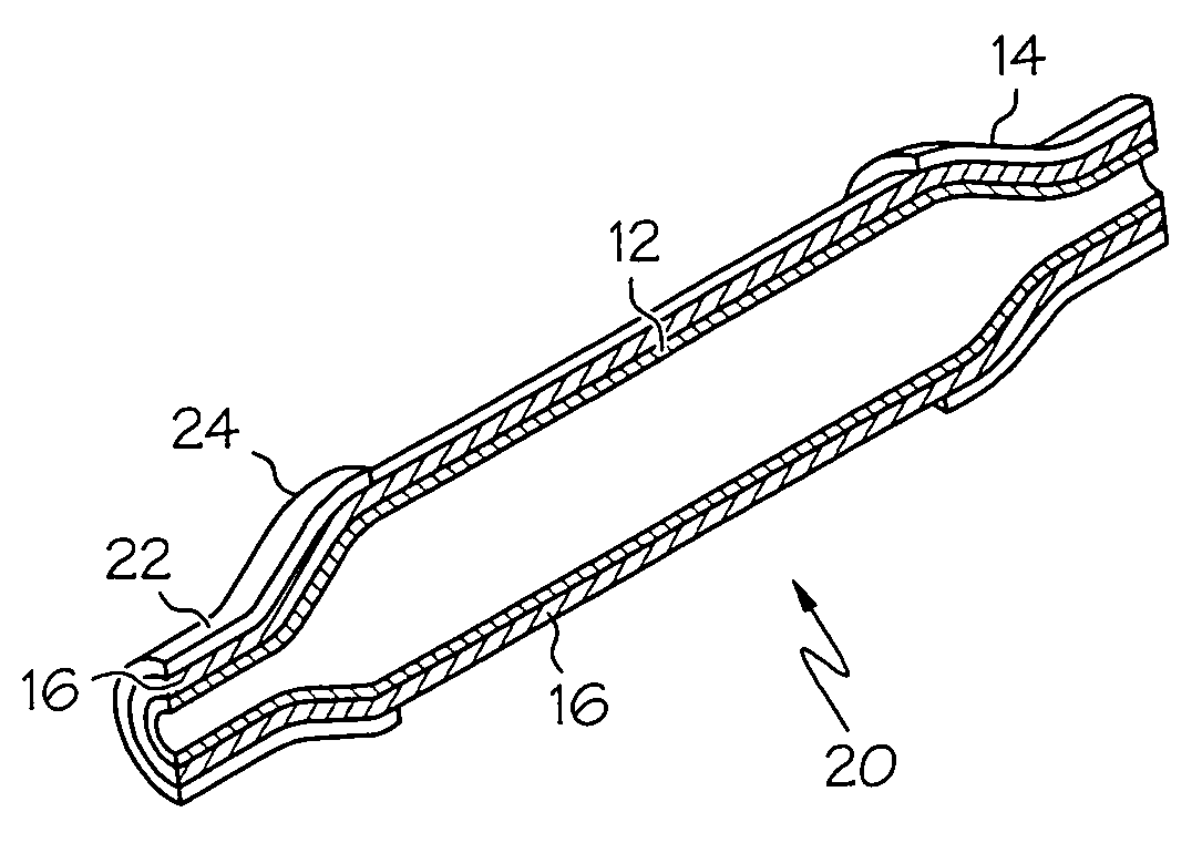
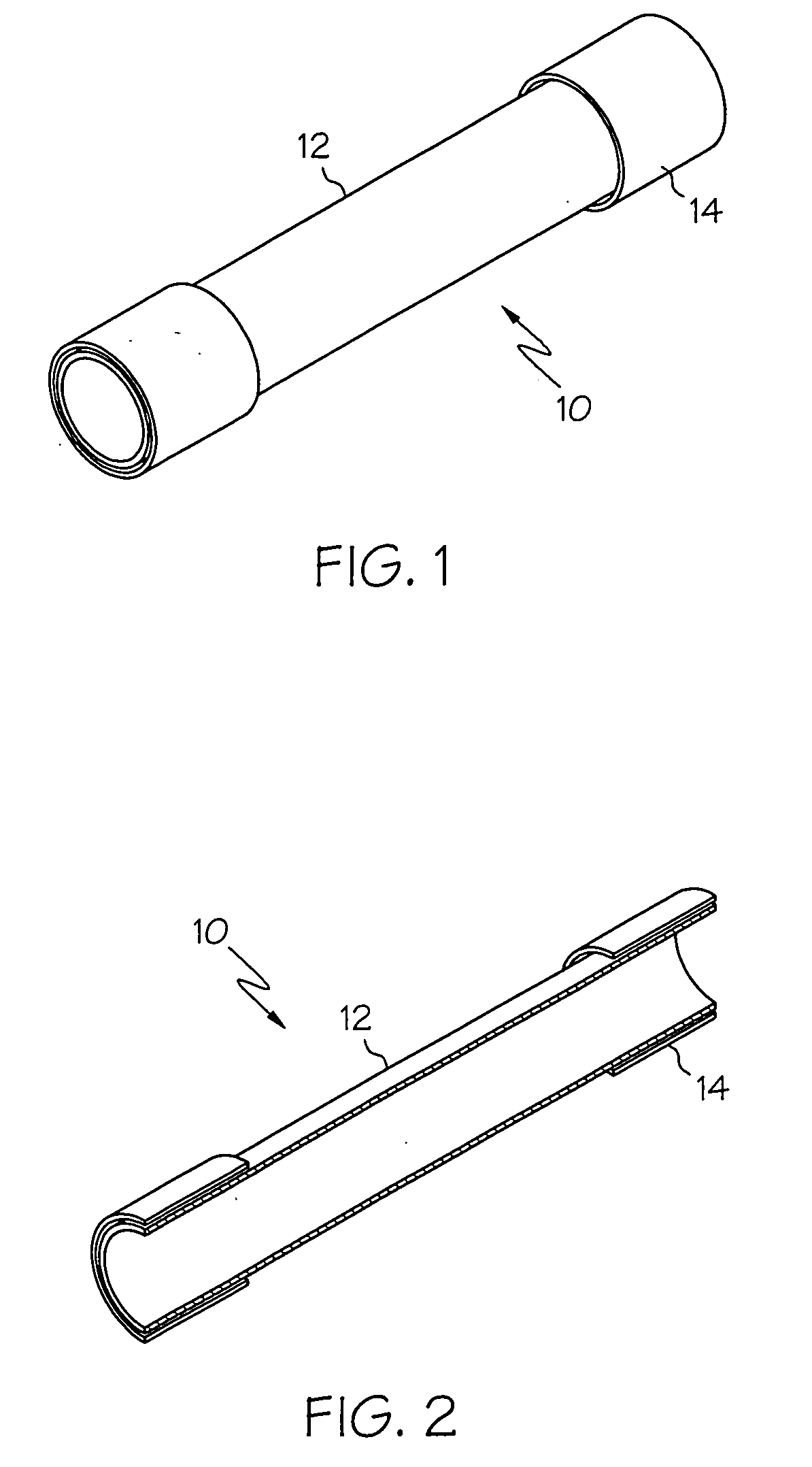
[0071] Turning now to the figures, FIG. 1 illustrates a base extruded tubular parison 12 formed from a first polymeric composition that has been manufactured using continuous extrusion of the base tubular parision 12 with intermittent extrusion of a crosslinkable layer 14. The crosslinkable layer is 14 is shown around each end of the tubular parison 12. Note that this tubular parison 12 is in the trimmed state. In actual production the ends could be longer if desired.

[0072]FIG. 2 is a cross sectional view of the same tubular parison 10 shown in FIG. 1 showing the base layer 12 defining the tubular parison and the crosslinkable layer 14. Crosslinking of layer 14 may be initiated as d...


PUM

PropertyMeasurementUnit
Compositionaaaaaaaaaa
Shrinkageaaaaaaaaaa
Melting pointaaaaaaaaaa

Abstract

A dilatation balloon for use in combination with a catheter device, the balloon having a waist, cone and body portion and having a first layer formed from a first polymeric composition, the balloon having a second layer disposed on at least a portion of the first layer, the second layer formed from a second polymeric composition which is crosslinked on at least a portion of the dilatation balloon, and methods of making and using the same.

Description

FIELD OF THE INVENTION [0001] The present invention relates to the area of catheters for performing medical procedures, and more particularly, to balloon catheters for use in angioplasty procedures. BACKGROUND OF THE INVENTION [0002] Balloon catheters are commonly used in relatively non-invasive medical procedures for the treatment of heart disease, such as in coronary angiography and percutaneous transluminal coronary angioplasty (PTCA). During such procedures, a balloon catheter is advanced through the vasculature of a patient such that the balloon is positioned proximate a restriction in a diseased vessel. The balloon is then inflated and the restriction in the vessel is opened. [0003] In a typical PTCA procedure, a hollow guiding catheter, a guidewire and a dilation catheter are inserted into the vasculature of a patient. The guiding catheter has a pre-shaped distal tip which is percutaneously introduced into the vasculature and advanced. An operator, such as a surgeon, twists a...

Claims


Application Information

Patent Timeline
IPC IPC(8): A61F2/958A61M29/00B29C35/02B29C48/09B29C48/21B29C49/00B29C49/04
CPCA61M25/10B29L2031/7542B29C35/0266B29C47/0023B29C47/065B29C49/0042B29C49/04B29K2021/00B29K2023/0608B29K2023/0633B29K2023/0641B29K2023/065B29K2027/06B29K2027/16B29K2027/18B29K2055/02B29K2069/00B29K2071/00B29K2075/00B29K2077/00B29K2079/08B29K2081/06B29K2105/258B29L2009/00B29L2022/022A61M2025/1075B29C48/09B29C48/21
Inventor BURGMEIER, ROBERTGOODIN, RICHARDDELANEY, JOSEPH JR.
Owner BOSTON SCI SCIMED INC
Why Eureka
Try Eureka