Method for controlling the mode of an electronic application
a technology of electronic applications and mode, applied in the direction of logic circuit coupling/interface arrangement, pulse technique, instruments, etc., can solve the problems of two extra pins and one or more extra pins, and achieve the effect of reducing the rise and fall tim
Inactive Publication Date: 2005-10-13
NXP BV
View PDF7 Cites 3 Cited by
- Summary
- Abstract
- Description
- Claims
- Application Information
AI Technical Summary
Benefits of technology
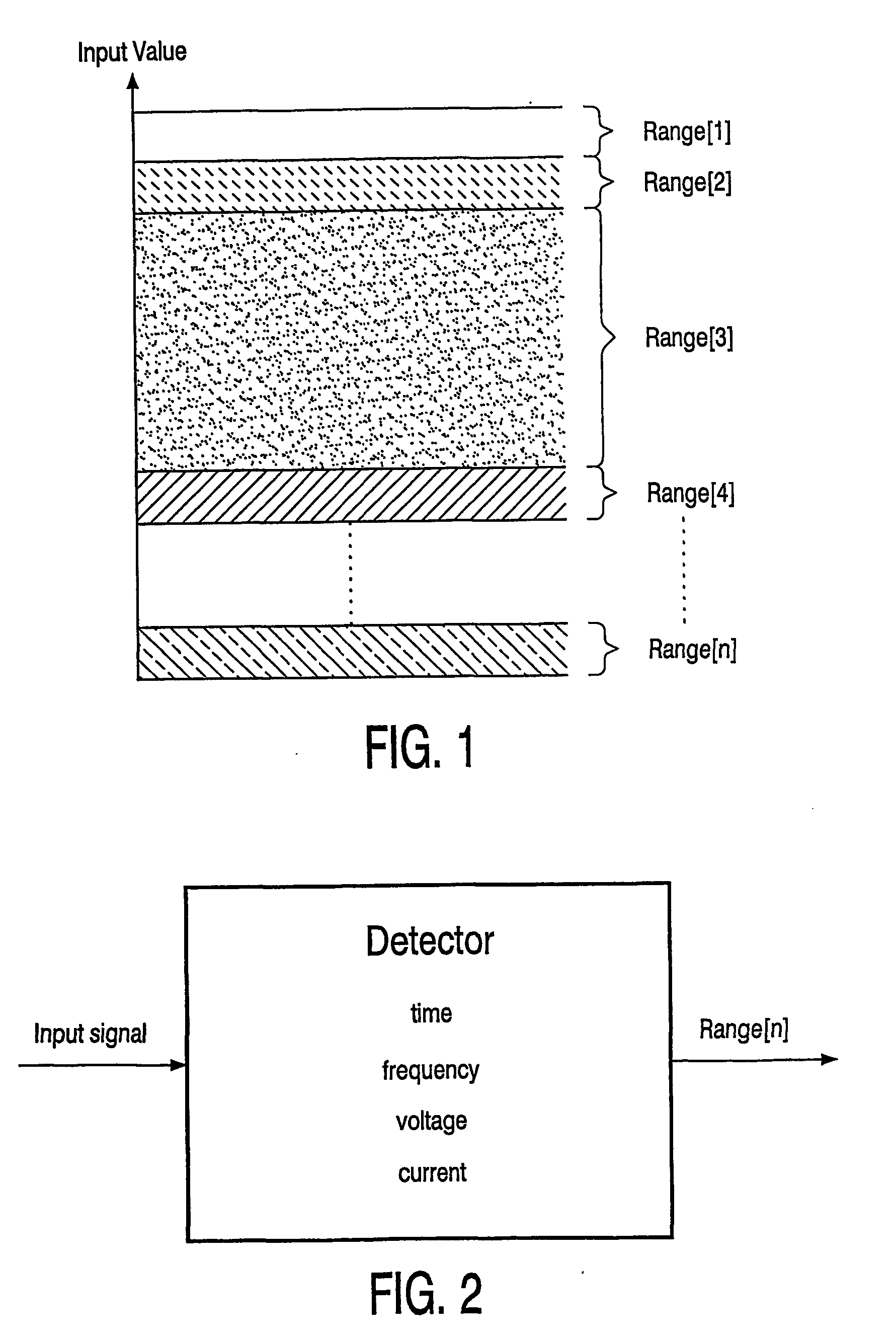
[0007] The inventive total input range is divided into a normal one and into an extended one. Input signals that are in the normal operating range refer for example to operations like amplify or switch. Input signals that are not within the normal operating range but are within the extended input range are used for mode recognition, e.g. standby mode, low EMI mode, measuring mode or configuration mode, with EMI standing for electromagnetic interference and low EMI mode is, for example, achieved by reducing the rise and fall time in a video amplifier.
Problems solved by technology
The disadvantage of the conventional power management is that one or more extra pins are needed.
The disadvantage of this system is that two extra pins are needed on the output power stage IC, that the output device has to be equipped with a digital interface and that the bus translator requires space within the output power stage IC.
Method used
View moreImage
Smart ImageViewing Examples

Examples
Embodiment Construction
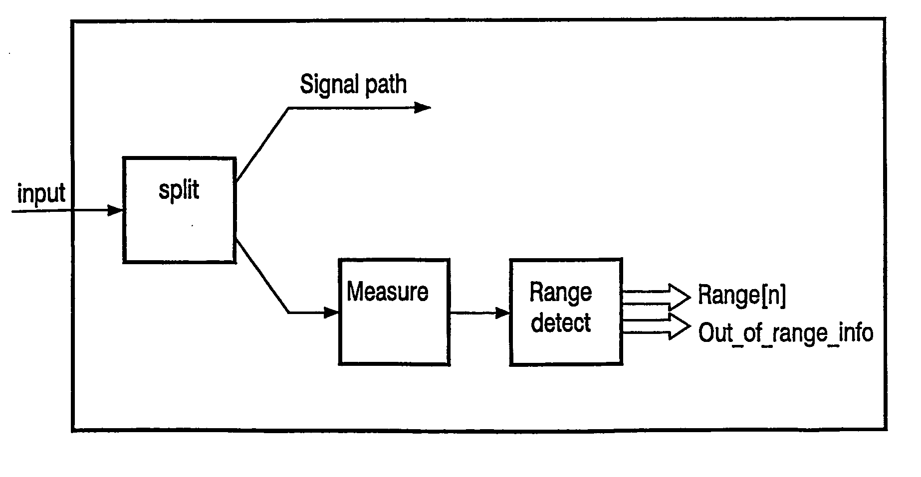
[0084] The preferred method for controlling the mode of an electronic application detects the range by measuring the value of a single-ended input.
[0085] The preferred circuitry that implements one of the claimed methods has an input signal that is generated by a current source and parallel to the first current source a second current source that is mounted as a reference with an “add current” switch connecting them.
Login to View More PUM
 Abstract
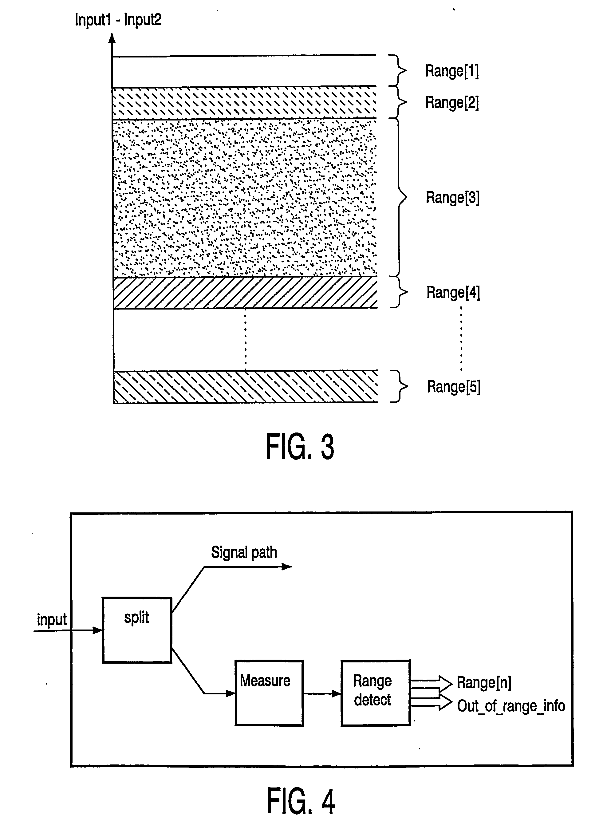
Method for controlling the mode of an electronic application like audio systems, display systems or portable equipment. The output stage of the electronic application controls the modes of the system, for example a normal mode, a standby mode or a sleep mode. The inventive method uses the existing connections for the input signals of the output stage. The allover level of the input signal or signals is divided into several ranges. One of the ranges is the normal operation range and the others who lay above or under the normal range are the extended ranges. The different ranges can be of different levels. The input signal can be a time, frequency, current or voltage. The inventive electronic application can be configured as a single-ended input as a differential input or as a multiple input.
Description
FIELD OF E INVENTION [0001] The invention relates to a method for controlling the mode of an electronic application, especially to the power management of output stages. These output stages are for example part of consumer electronics like audio systems, display systems or portable equipment. The driver stage controls the output stage and thus the modes of the system, for example a normal mode, a standby mode or a sleep mode. BACKGROUND OF THE INVENTION [0002] A conventional power management output power stage is part of a power stage IC. An input of the power stage IC is used to control the standby mode and / or other modes. In the conventional power management the connection from the driver IC to the power stage IC is made by means of a separate control connection. The disadvantage of the conventional power management is that one or more extra pins are needed. [0003] Another conventional power management uses a digital control bus. In this case the power management is executed by me...
Claims
Login to View More Application Information
Patent Timeline
 IPC IPC(8): G06F1/32H03K19/00H03K19/0175H03K19/173H04S7/00
CPCY02B60/1217G06F1/3203Y02D10/00
Inventor VAN RENS, FRANK J. P.MISDOM, JOHANNESKORDTS, JUERGEN
Owner NXP BV
Features
- R&D
- Intellectual Property
- Life Sciences
- Materials
- Tech Scout
- Unparalleled Data Quality
- Higher Quality Content
- 60% Fewer Hallucinations
Learn More Browse by: Latest US Patents, China's latest patents, Technical Efficacy Thesaurus, Application Domain, Technology Topic, Popular Technical Reports.
© 2025 PatSnap. All rights reserved.Legal|Privacy policy|Modern Slavery Act Transparency Statement|Sitemap|About US| Contact US: help@patsnap.com