Physical quantity sensor having multiple through holes

Active Publication Date: 2005-10-20
DENSO CORP
View PDF9 Cites 21 Cited by
  • Summary
  • Abstract
  • Description
  • Claims
  • Application Information

AI Technical Summary

Benefits of technology

[0009] In view of the above-described problem, it is an object of the present invention to pr

Problems solved by technology

Accordingly, the sensor has

Method used


Image

  • Physical quantity sensor having multiple through holes
  • Physical quantity sensor having multiple through holes
  • Physical quantity sensor having multiple through holes

Examples


first embodiment

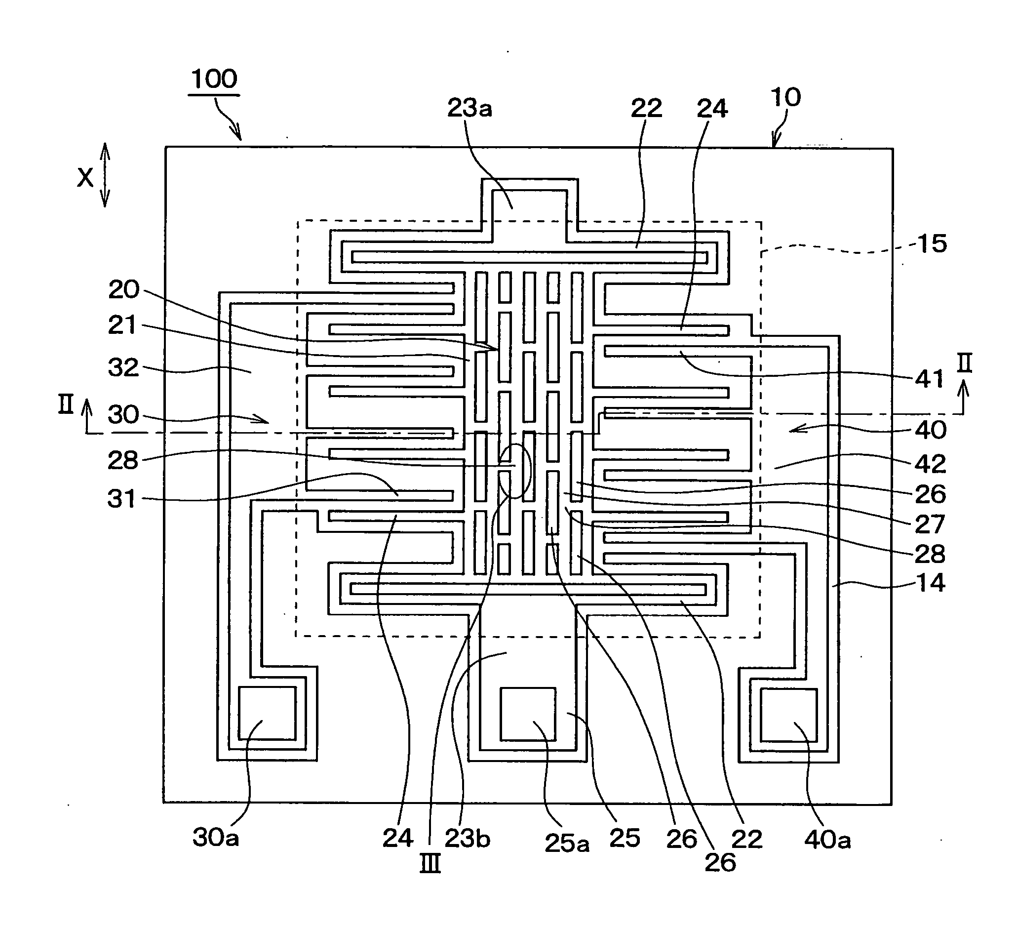
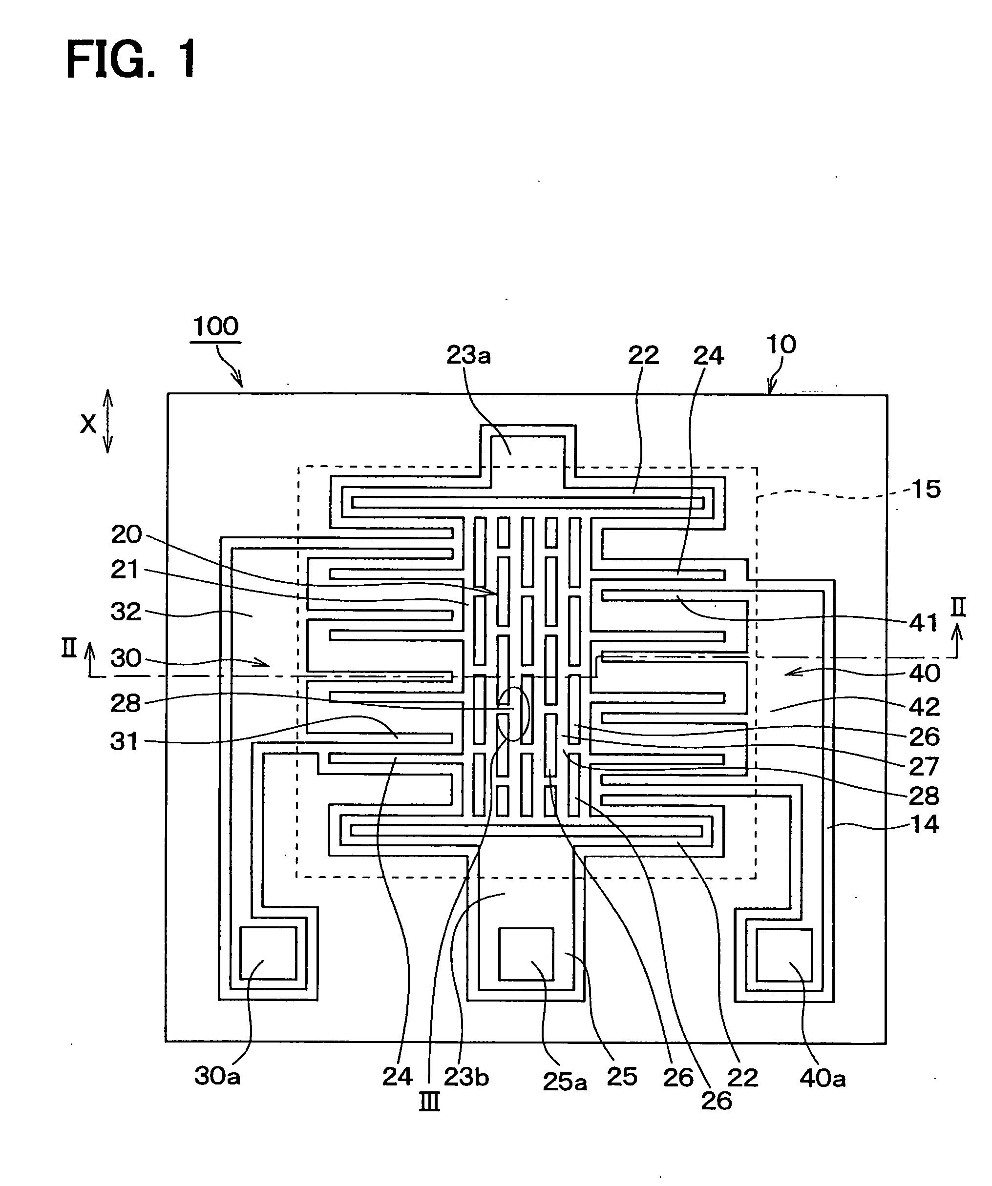
[0035] The inventors have preliminarily studied about a physical quantity sensor. FIG. 9 is a schematic plan view of the sensor. FIG. 10 is a schematic sectional view along the line X-X of FIG. 9. FIG. 11 is an enlarged view of the part XI of FIG. 9.

[0036] Such acceleration sensors are made by processing a semiconductor substrate 10 with a well-known micro-machine.

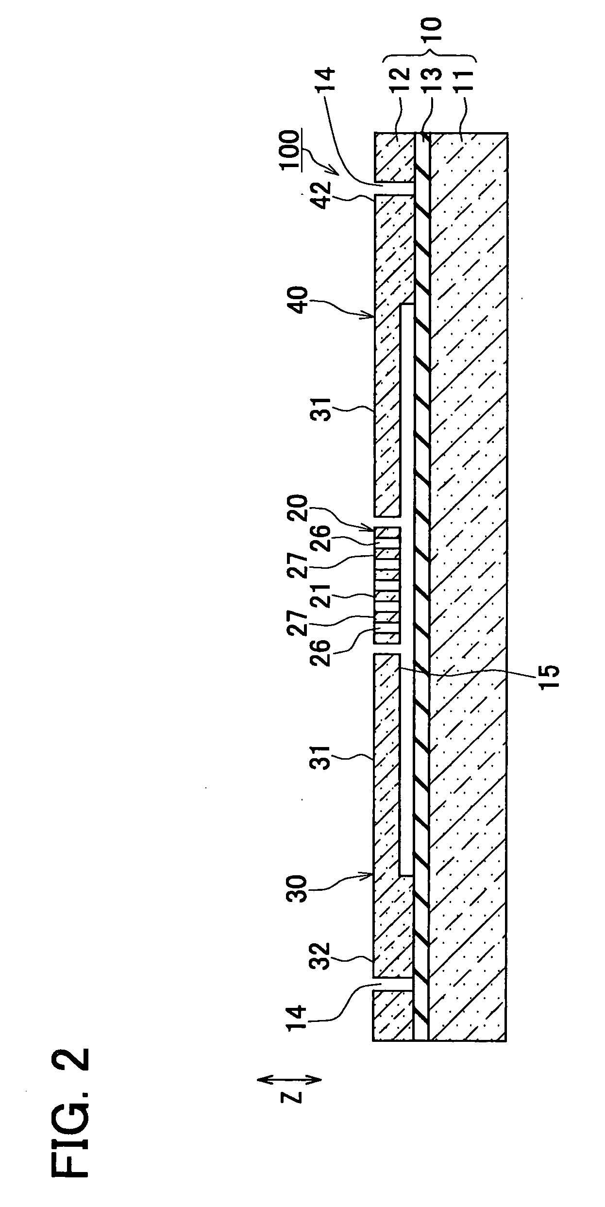
[0037] As shown in FIG. 10, the semiconductor substrate 10 of the experimental acceleration sensor is a rectangular SOI substrate 10 comprising a first silicon plate 11 as a supporting base plate, a second silicon plate 12 as a semiconductor layer, and an oxide film 13 as an insulating layer therebetween.

[0038] The second silicon plate 12 is trench-etched to form trenches 14, through holes 26, a movable part 20, and fixed electrodes 31 and 41. The movable part 20 has beam parts 22 and movable electrodes 24. The movable electrodes 24 are formed as one body with beam parts 22. The fixed electrodes 31 and 41 are arranged o...

second embodiment

[0110] The acceleration sensor 100 of the above embodiment of the present invention is characterized mainly by the junctions 28 of two or three straight parts of the hole frame 27, which are accomplished by arranging the rectangular through holes 26 in zigzag as shown in FIGS. 1 and 3.

[0111] Junctions 28 of two or three straight parts of the hole frame 27 can be accomplished by through holes 26 of other shapes shown in FIGS. 6 to 8.

[0112]FIG. 6 shows hexagonal through holes 26 in honeycomb-like arrangement.

[0113] In FIG. 7, junctions 28 of two or three straight parts of the hole frame 27 is accomplished by giving the shape of “L” to the through holes 26. In FIG. 8, junctions 28 of two or three straight parts of the hole frame 27 is accomplished by giving the shape of a cross to the through holes 26.

[0114] The through holes 26 of FIGS. 6 to 8 bring about the same effect as the through holes 26 of FIG. 1.

third embodiment

[0115] The inventors have further preliminarily studied about a dynamic-quantity sensor. According to the study by the inventors, it was learned that the following problem took place in the dynamic-quantity semiconductor sensor having such a movable part.

[0116] Namely, it was newly discovered that in the process where trenches are made in a semiconductor layer supported on a supporting base plate by etching to form the movable part, the etching rate during the release of the movable part depended on the trench width (see FIG. 16).

[0117] Accordingly, when releasing the movable part, etching could not be proceeded with at the portion, facing the trench, of the movable part having a wide trench width, namely, a wide-gap part (for example, 20 μm wide), and the release could not be accomplished.

[0118] In view of the above problem, a dynamic-quantity sensor according to a second embodiment of the present invention is provided.

[0119]FIG. 12 is a schematic plan view of an angular-veloci...


PUM


Abstract

A semiconductor physical quantity sensor includes: a substrate; a semiconductor layer supported on the substrate; a trench disposed in the semiconductor layer; and a movable portion disposed in the semiconductor layer and separated from the substrate by the trench. The movable portion includes a plurality of through-holes, each of which penetrates the semiconductor layer in a thickness direction. The movable portion is capable of displacing on the basis of a physical quantity applied to the movable portion so that the physical quantity is detected by a displacement of the movable portion. The movable portion has a junction disposed among the through-holes. The junction has a trifurcate shape.

Description

CROSS REFERENCE TO RELATED APPLICATIONS [0001] This application is based on Japanese Patent Applications No. 2004-118887 filed on Apr. 14, 2004, and No. 2004-133657 filed on Apr. 28, 2004, the disclosures of which are incorporated herein by reference. FIELD OF THE INVENTION [0002] The present invention relates to a physical quantity sensor having multiple through holes. BACKGROUND OF THE INVENTION [0003] A dynamic-quantity semiconductor sensor (i.e., a physical quantity sensor) of prior art comprises a base plate and a semiconductor layer. The semiconductor layer is supported on the base plate. Through trenches are made in the semiconductor layer by etching. The semiconductor layer has a movable part, which is defined by the trenches and released from the base plate. The sensor is, for example, disclosed in Japanese Patent Application Publication No. 2001-91265. [0004] The dynamic-quantity semiconductor sensor detects the applied dynamic quantity, i.e., the physical quantity, based ...

Claims


Application Information

Patent Timeline
IPC IPC(8): B81B3/00G01C19/56G01P15/125
CPCG01P15/125G01C19/5719
Inventor MURATA, MINORUYOKOYAMA, KENICHIASAI, MAKOTO
Owner DENSO CORP
Why Eureka
Try Eureka