Zero-G emulating testbed for spacecraft control system

a control system and zero gravity technology, applied in the field of zero gravity (0g) emulation of spacecraft, can solve the problems of complex dynamics characteristics of sensors and actuators, inability to fully investigate and measure the functional capability of spacecraft attitude/translation control systems with real physical units on the ground, and the dependence on various subsystem components, e.g., sensors, actuators, electronics, etc., to achieve the effect of reducing the complexity of the control system and reducing the complexity of the a control system and spacecraft control system and a spacecraft control system and a technology of the control system and a spacecraft control system a technology of the control system and zero gravity emulating testbed technology, applied in the field of a spacecraft emulating the field of a spacecraft, which is applied in the field of zero gravity and emulating the field of the control system emulating the field of the a a technology applied in the field of a spacecraft control system, which is applied in the field of a spacecra

Inactive Publication Date: 2005-10-20
CANADIAN SPACE AGENCY
View PDF32 Cites 80 Cited by
  • Summary
  • Abstract
  • Description
  • Claims
  • Application Information

AI Technical Summary

Benefits of technology

[0013] It is an object of the present invention to obviate or mitigate at least one disadvantage of previous ground-based testbed systems for testing a spacecraft and control systems employed in such spacecraft.

Problems solved by technology

The greatest challenge in implementing an advanced control system for spacecraft is that ground-based testing must take place in a 1-G environment, whereas the eventual hardware system will operate in a 0-G environment.
Validation and testing of the functional capability of spacecraft attitude / translation control systems with real physical units on the ground poses many challenges due to the effects of gravity.
The sensors and actuators have complex dynamics characteristics.
This implies that characteristics of the eventual control system, that depend on various subsystem components, e.g., sensors, actuators, electronics, control software, etc., can not be fully investigated and measured until the spacecraft is placed in orbit.
Due to the complexity of the dynamics associated with these actuators, a hardware test on the ground is required for verification.
Actuators, such as reaction wheels, torques, or gas-jet thrusters must be simulated in this method, which constitute its main limitation.
Also, the number of degrees-of-freedom is limited in this method.
Although the air bearing table system can be utilized to test physical units of spacecraft control systems including the sensors and actuators, this system is limited to a two-dimensional planar case that is not representative of reality, because the spacecraft dynamics in a planar environment are substantially simpler than in a 3-D environment.
The main problem with the air bearing system is the limited range of motion caused by the equipment affixed to the bearing limits.
Moreover, achieving all translational motion and rotational motion in a force / torque-free fashion is very difficult and requires a very complex system.
However, the following drawbacks exist: the actuators on the satellite control system are simulated; the simulation is not performed in a 3-D environment; and / or the range of rotational motion is limited.
Also, it is not possible in such known systems to test a spacecraft which has flexible elements, such as a solar panel.
There is no feedback in such systems, and it is not possible to change inertia, or parameters of a dynamics model of a spacecraft.
However, the free-fall test requires very expensive equipment and the test is sustainable for only a short period of time.

Method used


Image

  • Zero-G emulating testbed for spacecraft control system
  • Zero-G emulating testbed for spacecraft control system
  • Zero-G emulating testbed for spacecraft control system

Examples


Embodiment Construction

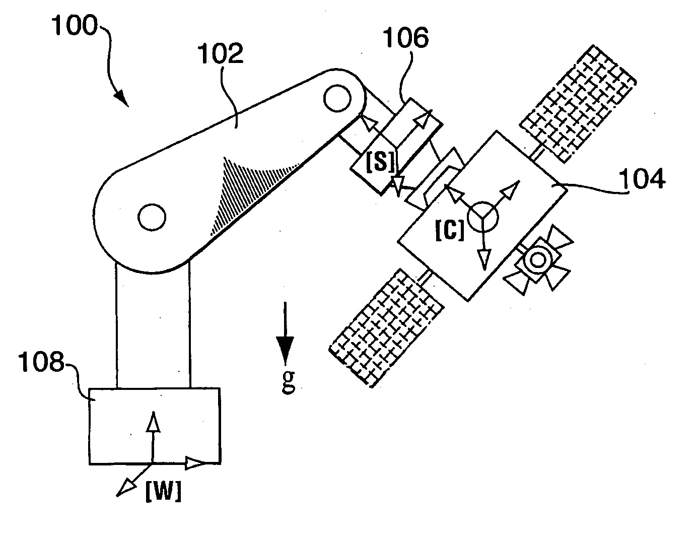
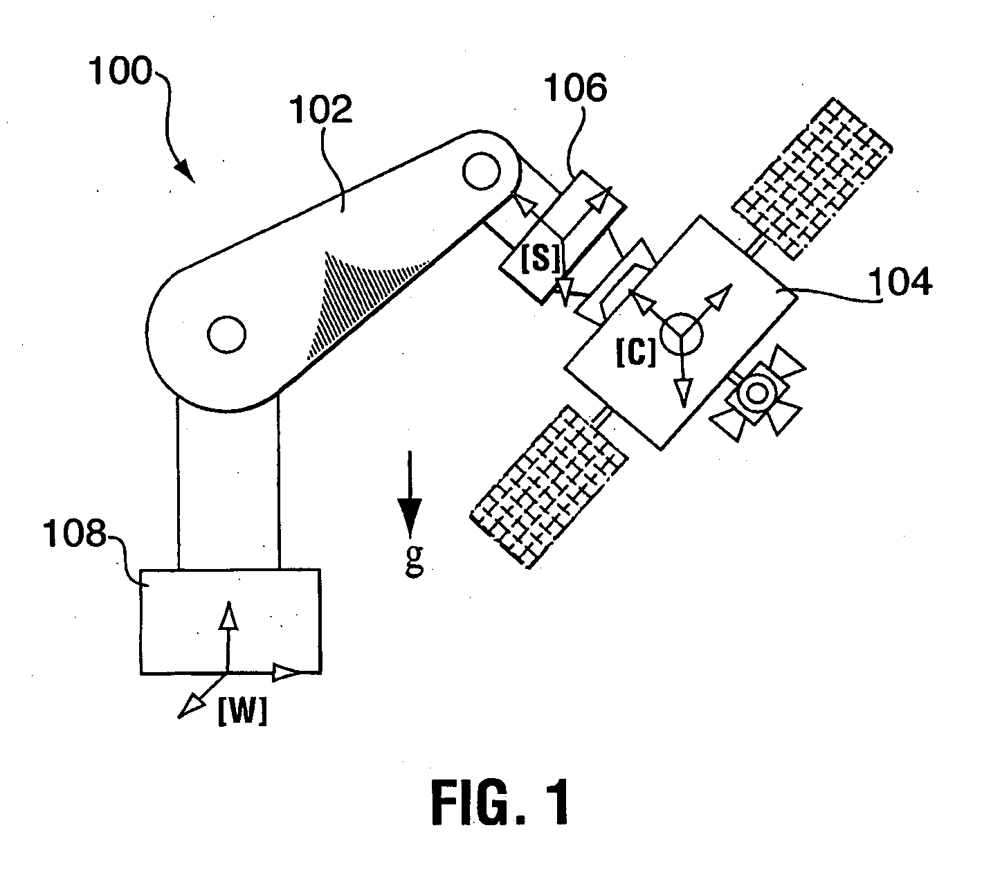
[0031] Generally, the present invention provides an emulation system having a control system that allows the testing of a satellite control system with all of its hardware in place, i.e. fully integrated. The emulation methodology is applicable to the case of either a rigid spacecraft or a flexible spacecraft, provided that the spacecraft's sensors and actuators are stowed to the rigid part of spacecraft in the case of a flexible spacecraft. Practically, the latter condition is not restrictive, as the actuators and sensors are usually placed rigidly in the satellite bus, while the satellite solar panels constitute the flexible elements. The control system is used to tune the mass properties and dynamic behavior of a rigid ground-spacecraft in a 1-G environment to those of a flight-spacecraft in 0-G. A six-axis force / moment sensor is placed at an interface of the ground-spacecraft and a manipulator. Signals received from the force / moment sensor, and in some cases signals relating to ...


PUM


Abstract

The present invention provides an emulation system having a control system that allows the testing of a satellite control system with all of its hardware in place, i.e. fully integrated. The emulation methodology is applicable to the case of either a rigid spacecraft or a flexible spacecraft, provided that the spacecraft's sensors and actuators are stowed to the rigid part of spacecraft in the case of a flexible spacecraft. Practically, the latter condition is not restrictive, as the actuators and sensors are usually placed rigidly in the satellite bus, while the satellite solar panels constitute the flexible elements. The control system is used to tune the mass properties and dynamic behaviour of a rigid ground-spacecraft in a 1-G environment to those of a flight-spacecraft in 0-G. A six-axis force/moment sensor is placed at an interface of the ground-spacecraft and a manipulator. Signals received from the force/moment sensor, and in some cases signals relating to the position and velocity of manipulator joints, are received into the control system.

Description

CROSS-REFERENCE TO RELATED APPLICATIONS [0001] This application claims the benefit of U.S. Provisional Application No. 60 / 532,890, filed Dec. 30, 2003, which is incorporated herein by reference.FIELD OF THE INVENTION [0002] The present invention relates generally to the emulation of zero-gravity conditions in an environment where the effects of gravity are otherwise present. More particularly, the present invention relates to zero-gravity (0-G) emulation of a spacecraft in an earthbound (1-G) laboratory environment using a controlled manipulator. BACKGROUND OF THE INVENTION [0003] The greatest challenge in implementing an advanced control system for spacecraft is that ground-based testing must take place in a 1-G environment, whereas the eventual hardware system will operate in a 0-G environment. Simulation is widely used for characterizing the functional behavior of spacecraft control systems. However, it is of vital importance to be able to test and validate the system performance...

Claims


Application Information

Patent Timeline
Patent Type & Authority Applications(United States)
IPC IPC(8): B64G5/00B64G7/00G06F19/00
CPCB64G7/00
Inventor AGHILI, FARHAD
Owner CANADIAN SPACE AGENCY
Why Eureka
Try Eureka