Security device for a transponder

a transponder and security technology, applied in the field of transponder security devices, can solve the problems of inability to perform other actions, inability to address the transponder, and inability to meet the needs of the transponder,

Active Publication Date: 2005-10-20
ATMEL GERMANY
View PDF12 Cites 22 Cited by
  • Summary
  • Abstract
  • Description
  • Claims
  • Application Information

AI Technical Summary

Benefits of technology

[0032] It is therefore an object of the present invention to provide a very secure deactivation of a transponder. In particular, besides a permanent deactivation (kill mechanism), a temporary deactivation (cloak mechanism), if required, is to be possible as well. Another object is for the function of the temporary and / or permanent deactivation to be made available by the authorized user to other users as well, as necessary, in a simple manner. A further object is for the password for the deactivation to be modifiable without a resulting restriction of security.

Problems solved by technology

After temporary or permanent deactivation, the transponder is no longer capable of being addressed via an electromagnetic field transmitted by a base station and send modulated response signals back to the base station.
It is also incapable of performing other actions such as, for example, a storage process or a programming process.
Nevertheless, this requires extraordinary effort, particularly in the case of many products equipped with transponders, and is therefore not very feasible.
Moreover, the transponders frequently cannot be removed, because they are embedded in the product or even are a component of these products.
A problem, however, is a desired verification of whether inoperability of the transponder, which was associated with the destruction, was achieved.
A disadvantage of this solution, however, is that, for example, the flip-flop can lose its stored value due to operating voltage variations above the POR threshold, so that access to the transponder is again possible.
However, this solution as well has significant disadvantages.
This type of security sink results inevitably in that certain information must be divulged by the authorized user to the developer and / or manufacturer of the transponder equipped with such a security device for implementing the security system, for example, by an employed password and by specific circuitry design of a security device.
Admittedly, these companies of course handle all of this information very confidentially, but an element of risk always remains that the confidential information reaches an unauthorized user.
Another problem is that users pragmatically tend to limit the total number of employed passwords in order to limit as much as possible their own logistic efforts, especially for reasons of cost.
All in all, however, this means that the current, generally known security devices, which use a transponder-internal protocol mechanism for realizing the kill / cloak function, do not offer sufficient security, particularly for security-relevant applications.
This is a situation that is not acceptable, especially in the case of security-relevant products, and is not accepted, most notably, by many customers of such products.

Method used


Image

  • Security device for a transponder
  • Security device for a transponder
  • Security device for a transponder

Examples


Embodiment Construction

[0077] In the figures, the same or functionally identical elements, data, and signals, if not specified otherwise, are given the same reference characters.

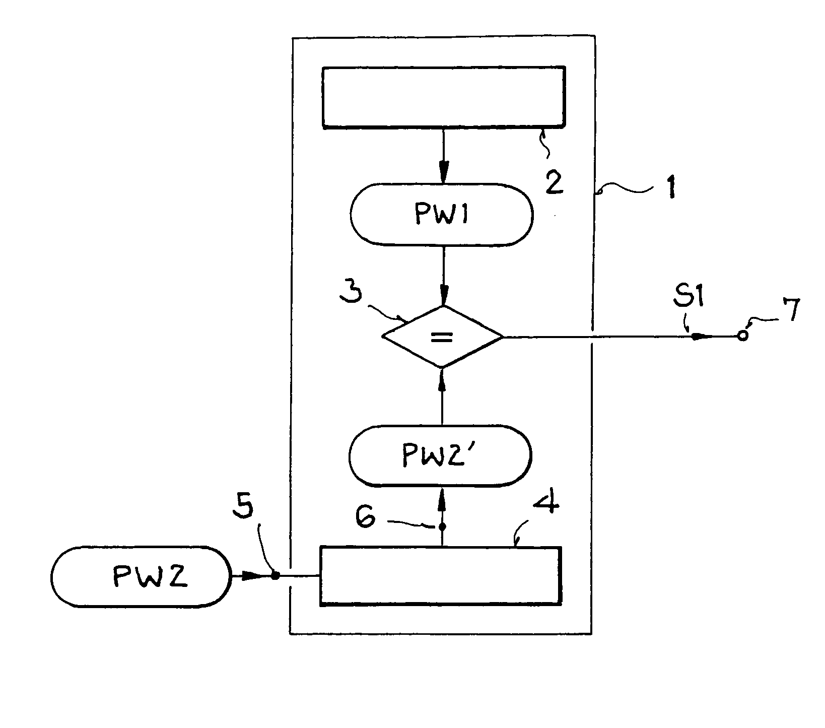
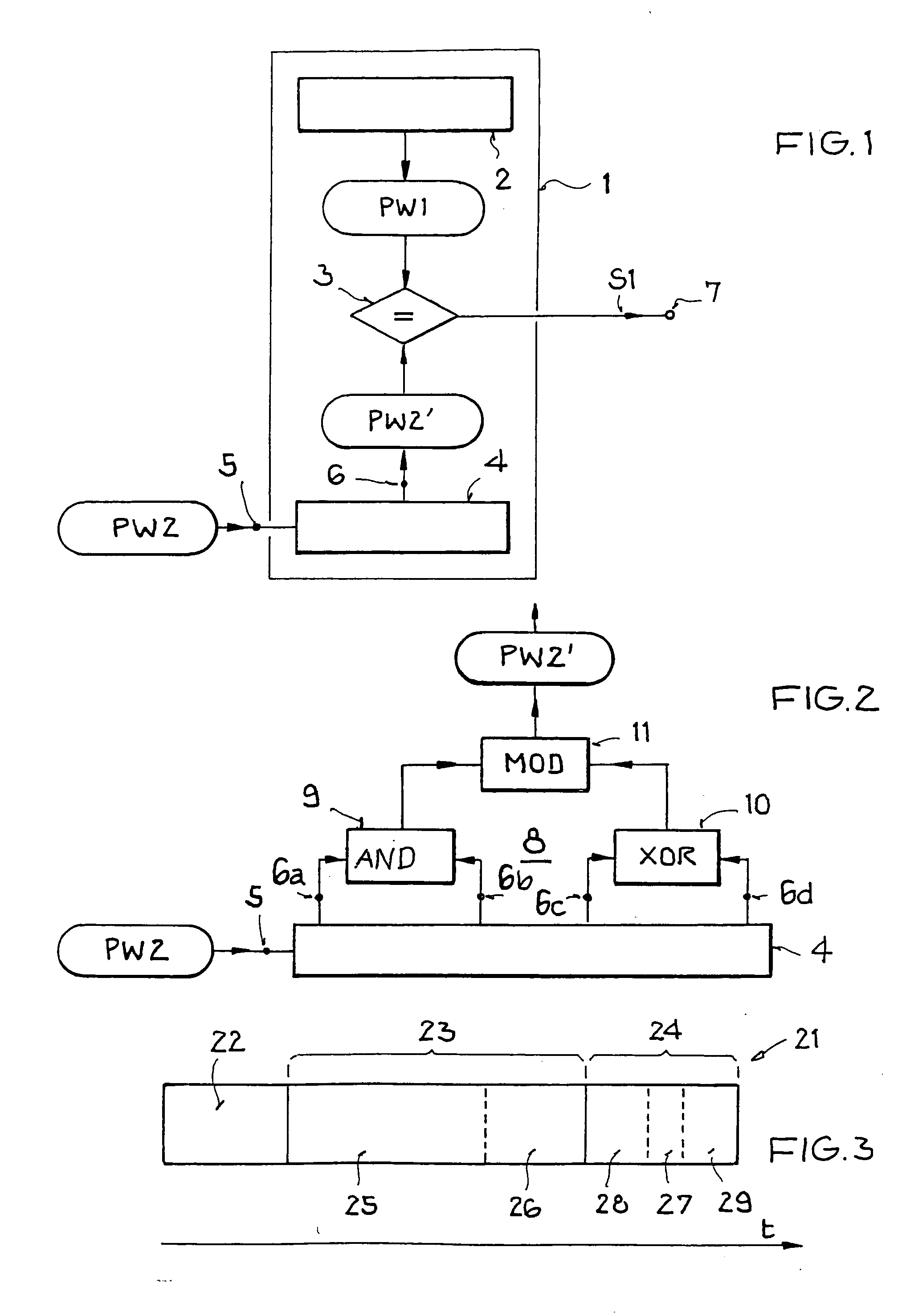
[0078]FIG. 1 illustrates a structure and operating principle of a security device according to an example embodiment of the present invention for activating and / or deactivating a kill mechanism or a cloak mechanism.

[0079] In FIG. 1, the security device of the invention is designated with the reference character 1. The security device 1 has a memory 2, a comparison device 3, and a cryptologic device 4.

[0080] The memory 2 can be any desired memory, for example, a common volatile or nonvolatile semiconductor memory, such as DRAM, SRAM, EPROM, EEPROM, etc., or a hardwired logic element having a memory functionality such as, for example, an FPGA or PLD circuit. The memory 2 can be made a component of the memory of a transponder or be separate from the security device 1. A first, open password PW1 is stored in the memory 2.

[0081] Th...


PUM


Abstract

A security device for a transponder with a kill and/or cloak function is provided. The security device includes a memory device, in which a first, open password is stored, an input, into which a second, secret password is coupled, a cryptologic device, which is connected to the input and generates a checksum from the second password, and a comparison unit, which compares the checksum and the first password and which upon an agreement generates a kill and/or cloak control instruction to activate and/or deactivate a kill and/or cloak mechanism, which can be tapped at an output. A method for configuring a security device and a method for operating a transponder, and a transponder having the security device are also provided.

Description

[0001] This nonprovisional application claims priority under 35 U.S.C. § 119(a) on German Patent Application Nos. DE 102005005436.6 and DE 102004018557.3, which were filed in Germany on Feb. 5, 2005 and Apr. 14, 2004, respectively, and which are both herein incorporated by reference. BACKGROUND OF THE INVENTION [0002] 1. Field of the Invention [0003] The present invention relates to a security device for a transponder having a security function, particularly with a kill and / or cloak function. The invention further relates to a method for configuring a security means, to a method for operating a transponder, and to a transponder. [0004] 2. Description of the Background Art [0005] The invention falls within the realm of transponder technology and in particular within the field of contactless communication for the purpose of identification. Although it can be used in principle in any communication system, the present invention and its underlying problems are explained with reference to...

Claims


Application Information

Patent Timeline
Patent Type & Authority Applications(United States)
IPC IPC(8): G06F1/00G06F12/14G06F21/31G06K7/00G06K19/073G07F7/10H04B1/59H04L9/30H04L9/32
CPCG06F21/31H04L9/32G06K19/07345H04L9/3226H04L9/3236H04L2209/805
Inventor FRIEDRICH, ULRICHZIEBERTZ, DIRK
Owner ATMEL GERMANY
Why Eureka
Try Eureka