Antenna module
- Summary
- Abstract
- Description
- Claims
- Application Information
AI Technical Summary
Benefits of technology
Problems solved by technology
Method used
Image
Examples
embodiment 1
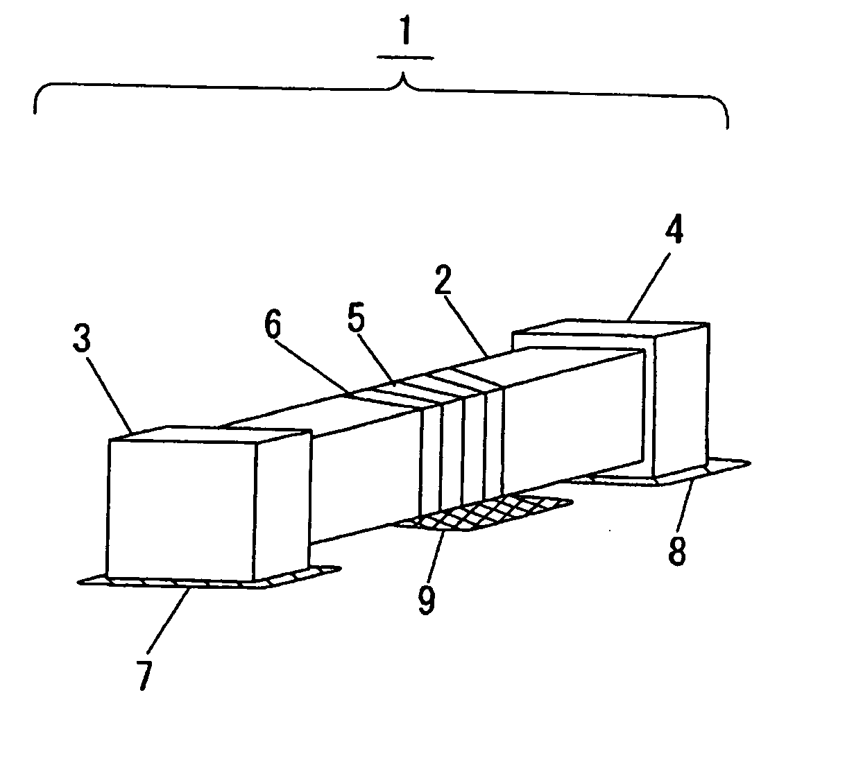
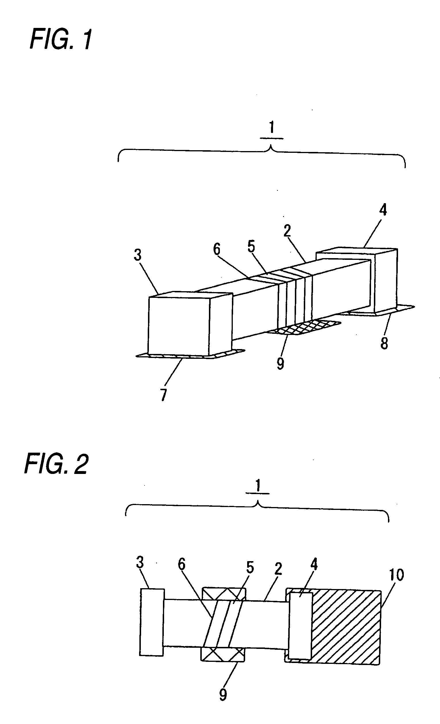
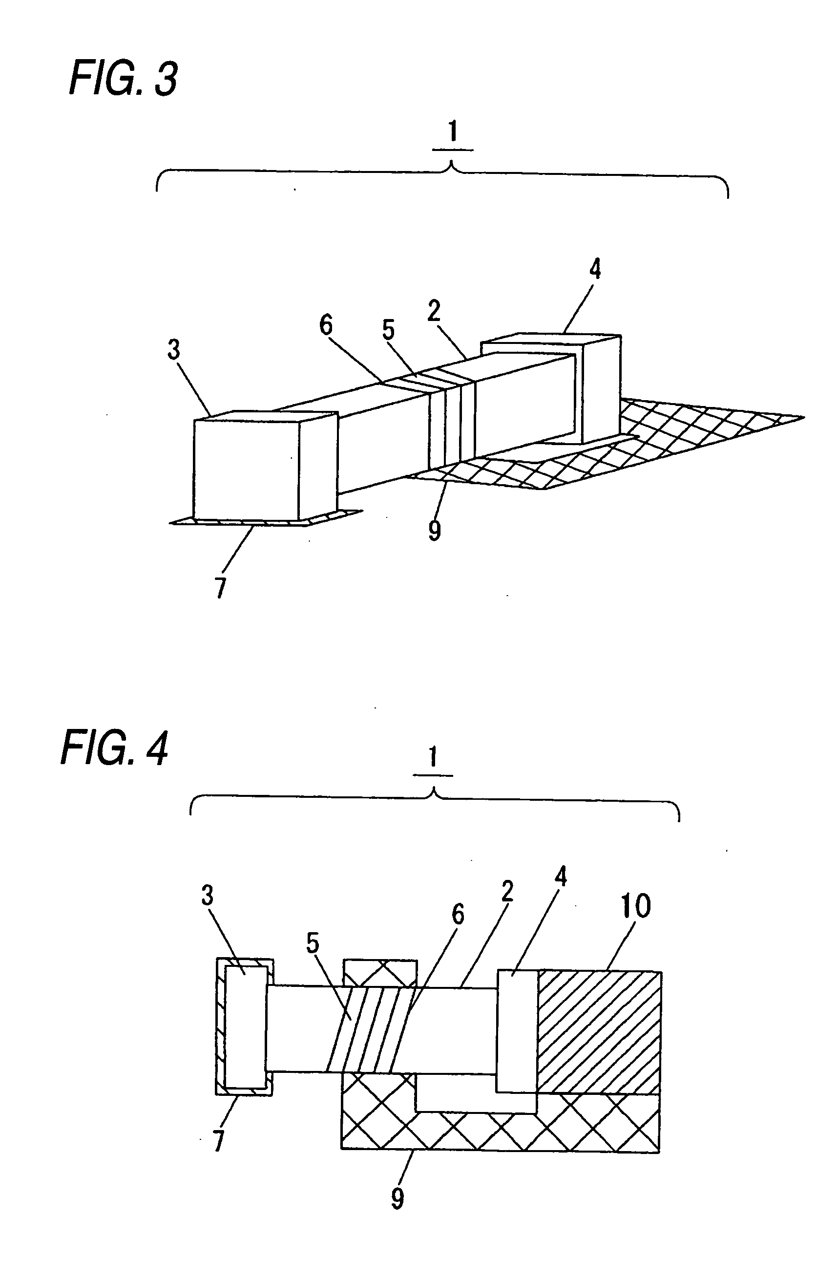
[0039]FIG. 1 and FIG. 3 are perspective views of the antenna module in the embodiment 1 of the invention, and FIG. 2, FIG. 4 and FIG. 7 are structural views of the antenna module in the embodiment 1 of the invention. FIG. 5 is an equivalent circuit diagram of the antenna module shown in FIG. 3. FIG. 8 is the equivalent circuit diagram of the antenna module shown in FIG. 7. FIG. 16 and FIG. 17 are perspective views of the other antenna modules in the embodiment 1 of the invention.
[0040] Numeral 1 designates the chip antenna, 2 designates the substrate, 3 and 4 are terminal parts, 5 is the helical part, 6 is spiral grooves, 7 is the feeding portion, 8 is the open portion, and 9 is the capacitive conductor. The mounting body mounting these members thereon is not shown.
[0041] The chip antenna 1 is composed in that the terminal parts 3, 4 are provided at both ends of the substrate 2, a helical part 5 is defined by forming a spiral grooves 6 formed in such a manner that a conductive fil...
embodiment 2
[0085] In Embodiment 2, explanation will be made to the antenna module having a plurality of chip antennas. FIGS. 9, 10, 11, and 13 are the structures of the antenna module in Embodiment 2 of the invention. FIG. 12 is the equivalent circuit diagram of one part of the antenna module shown in FIG. 9.
[0086]FIGS. 9, 10 and 11 show the structures connected in series with the two chip antennas. Numerals 11 designates the connected conductor and 12 is the antenna module. The connected conductor 11 connects in series the two chip antennas. This connected conductor is formed with the mounted land, the soldered face or the metal film, and if the width direction is made not largely exceed the width direction of the chip antenna 1, the antenna module is miniaturized. The same is applied to the capacitive conductor. The signal current is sent to the chip antenna 1 via the feeding portion 7, and since the chip antenna 1 is connected in series via the connected conductor 11, the signal current is...
embodiment 3
[0103]FIG. 14 is a structural view of the electronic instrument in the embodiment 3 of the invention. The electronic instrument shown in FIG. 14 is the notebook personal computer, portable terminal, and portable telephone, and they are incorporated with the antenna module mounted with the chip antenna discussed in Embodiments 1 and 2.
[0104] Numeral 30 designates the case, 32 designates the high frequency circuit, 33 is a processing circuit, 34 is a control circuit, and 35 is an electric power source.
[0105] The case 30 is, for example, a case of the portable telephone, or of the notebook personal computer, and the case 30 may contain a display, a memory, a hard disc or an external storage medium.
[0106] The high frequency circuit applies high frequency signal current to the antenna module 31, or receives the high frequency signal received at the antenna module 31 and detects waves. The high frequency circuit contains a power amplifier necessary to signal transmission, a low noise a...
PUM
 Abstract
Description
Claims
Application Information
 - R&D
- Intellectual Property
- Life Sciences
- Materials
- Tech Scout
- Unparalleled Data Quality
- Higher Quality Content
- 60% Fewer Hallucinations
Browse by: Latest US Patents, China's latest patents, Technical Efficacy Thesaurus, Application Domain, Technology Topic, Popular Technical Reports.
© 2025 PatSnap. All rights reserved.Legal|Privacy policy|Modern Slavery Act Transparency Statement|Sitemap|About US| Contact US: help@patsnap.com


