Surface mount type piezoelectric vibrator and manufacturing method of the same, an oscillator with the surface mount type piezoelectric vibrator, an electronic unit, and a wave clock

Inactive Publication Date: 2007-04-12
SII CRYSTAL TECH
View PDF3 Cites 6 Cited by
  • Summary
  • Abstract
  • Description
  • Claims
  • Application Information

AI Technical Summary

Benefits of technology

[0060] The object of the present invention is to provide a small-sized surface mount type piezoelectric vibrator with reduced mounting area, easy production and low cost in light of the above-mentioned conventional problems.
[0061] Furthermore, the object of the present invention is to provide a manufacturing method for a surface mount type piezoelectric vibrator that allows the maximization of electrical contact terminals brought into contact with surface mount type piezoelectric vibrators having two-directional lead terminals arranged in short pitches on a section bar and arranged in a matrix on a lead frame with high density through the effective use of a width ⅓ to ⅕ smaller than a length and the simultaneous measurement of these vibrators all together with a quick measurements of individual vibrators, in an electrical test process of a surface mount type piezoelectric vibrator manufacturing process. It is also to provide a manufacturing method for a surface mount type piezoelectric vibrator manufacturing process that makes it possible to simultaneously testing more of the surface mount type piezoelectric vibrators with electrical contact terminals in contact with a plurality of surface mount type piezoelectric vibrators arranged with high density without repeated electrical contact terminal contacts, and without any influence on the frequency of adjacent vibrators, and allocate resulting saved time to measurements for performance characteristic measurement items for measurement accuracy guarantee, thus allowing reliability and quality improvements and uses the lead frame.

Problems solved by technology

However, since the cylinder-type package piezoelectric vibrator is cylindrical, the position thereof unstable or two elongate lead terminals are bendable, so that unlike other electronic parts, the cylinder-type package piezoelectric vibrator cannot be, as it is, surface-mounted using an automatic mounting machine.
However, in the press work that moves the die and punch vertically, a tip of the electrode section and the punch are interfered with each other when secondly folding in cross-sectional u-shape.
Accordingly, complicated press equipments are required and it becomes difficult to work the cross-sectional u-shaped electrode terminal by the folding.
When using the method of welding by applying voltage for bridging the outer lead in contact with the upper electrode terminal for the electrical continuity, the outer lead and upper electrode terminals need to be in contact with each other between two upper and lower bonding electrodes, while it becomes very difficult that they are disposed between the bonding electrodes in case of the cross-sectional unshaped electrode terminal.
The reason is that the lower electrode terminal is disposed at the reverse side opposite to the outer lead of the upper electrode terminal, whereby it is increasingly difficult that the bonding electrode at the lower side directly supports the lower surface.
It is difficult to remove the resin burr on the vertical section by means of the general deburring.
If so, the function of the vibrator is hindered due to the short-circuiting of the vibrator.
Consequently, so the margin may be given in the height direction as to evade the contact between the sealing tube and the lower electrode terminal, and on the other hand, there is the problem that the height of the body of the surface mount type piezoelectric vibrator increases.
Next, the method for manufacturing the conventional surface mount type piezoelectric vibrator has the following problems.
In a process for bending the outer lead 3 in advance, misalignment of the turning angle difference θ for the outer lead 3 results in an insufficient bend in the outer lead 3, thus making impossible the alignment of the required bonding point in some cases.
In a process for sealing the sealing tube 5 and the airtight terminal 1, however, there is a dimensional deviation in the longitudinal direction of the vibrator 6.with a resultant deviation in the cutting accuracy for the outer lead 3, thus making the above alignment insufficient in some cases.
Particularly machining using a transfer jig will make it impossible to proceed with subsequent processes properly under any of the above-mentioned situations.
In addition, an insufficient alignment of the sealing tube 5 described above can result in warpage in the lead frame 60 in the longitudinal direction thereof because of the contact of the dummy terminal 32 facing the electrode terminal 33 with the sealing tube 5 on the lead frame 60.
In the resin molding process that follows the bonding process described above, an incorrect alignment of the vibrator 6 in molds also results in not only problematic electrode terminal 33 bonding.
The incorrect alignment also results the problematic partial exposure of the vibrator 6 from mold resin the resultant incorrect formation of the periphery of the vibrator 6.
However, the resin molding process for a conventional surface mount type piezoelectric vibrator 31 has problematic points as described below.
The difference in size of the electrode terminal 33 across the width of the surface mount type piezoelectric vibrator 31 can cause contact of a cutting punch with the mold resin thereof, thus resulting in problematic resin chips due to lead cutting.
As described above, the resin chipping resulting from resin molding has an adverse influence on the product performance of the surface mount type piezoelectric vibrator 31.
Individual surface mount type piezoelectric vibrators 31 are problematically difficult to handle so as to guarantee-the performance characteristics thereof.
However, the higher cavity density would result in a problematically complicate mold for the resin mold construction.
In other words, the formation of notch grooves in the lead frame 60 can lead to the expansion of notch groove formation surfaces, thus resulting in warpage in these surfaces.
Any warpage in the lead frame 60 will make it impossible to proceed with subsequent processes properly when the lead frame is mechanically carried and aligned.
If an attempt is made to meet the necessity of enhancing the layout density of the lead frame relative to the lead frame 60 on which more electrical contact terminals are brought into contact with electronic parts as described above, piezoelectric vibrators 6 can be affected by the influence of the frequencies of piezoelectric vibrators 6 oscillating each other due to the distance between adjacent surface mount type piezoelectric vibrators 31, thus making it difficult to make correct frequency measurements.

Method used


Image

  • Surface mount type piezoelectric vibrator and manufacturing method of the same, an oscillator with the surface mount type piezoelectric vibrator, an electronic unit, and a wave clock
  • Surface mount type piezoelectric vibrator and manufacturing method of the same, an oscillator with the surface mount type piezoelectric vibrator, an electronic unit, and a wave clock
  • Surface mount type piezoelectric vibrator and manufacturing method of the same, an oscillator with the surface mount type piezoelectric vibrator, an electronic unit, and a wave clock

Examples


first embodiment

[0153] First, the construction of the surface mount type piezoelectric vibrator will be described with reference to FIGS. 2 to 6.

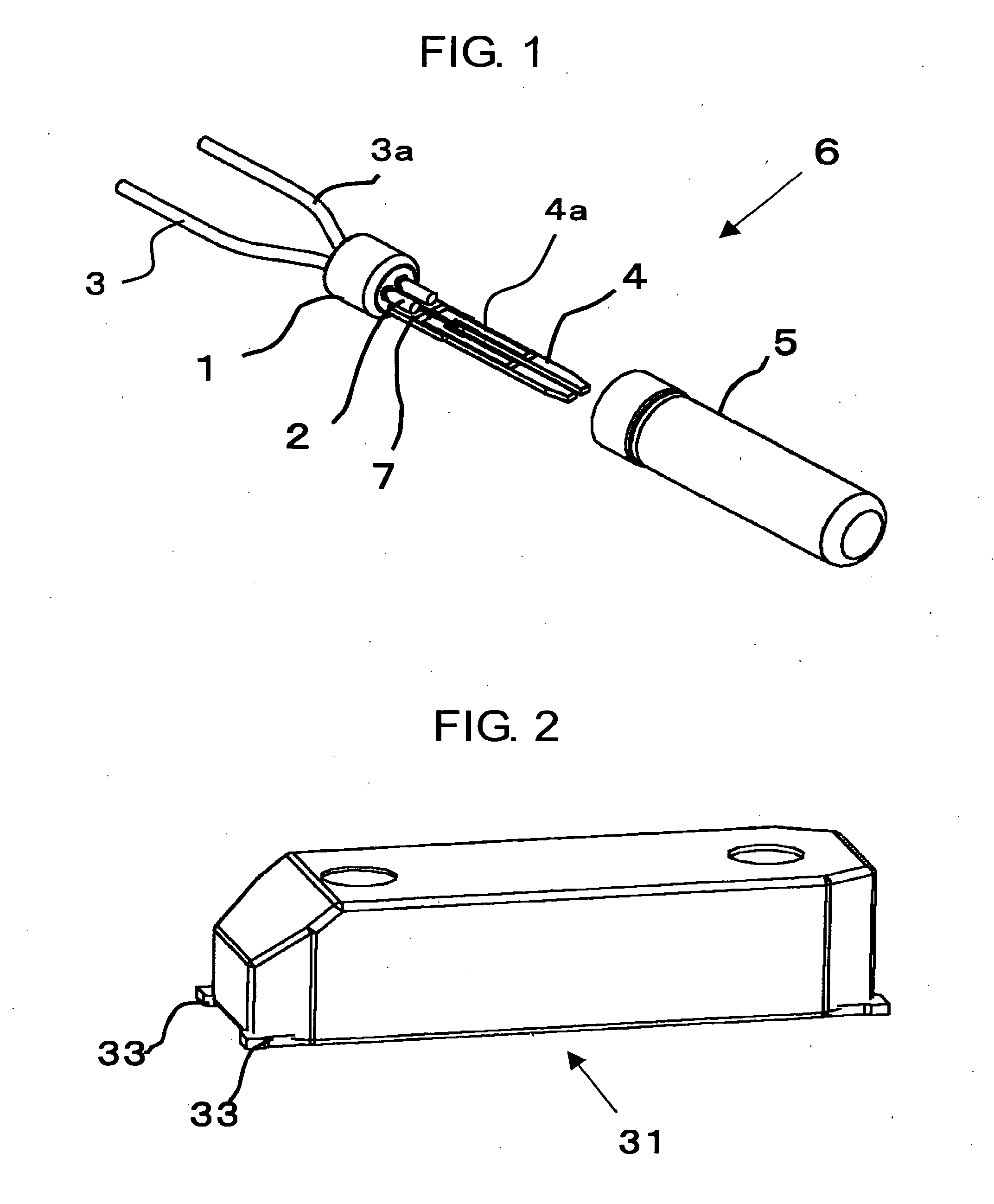
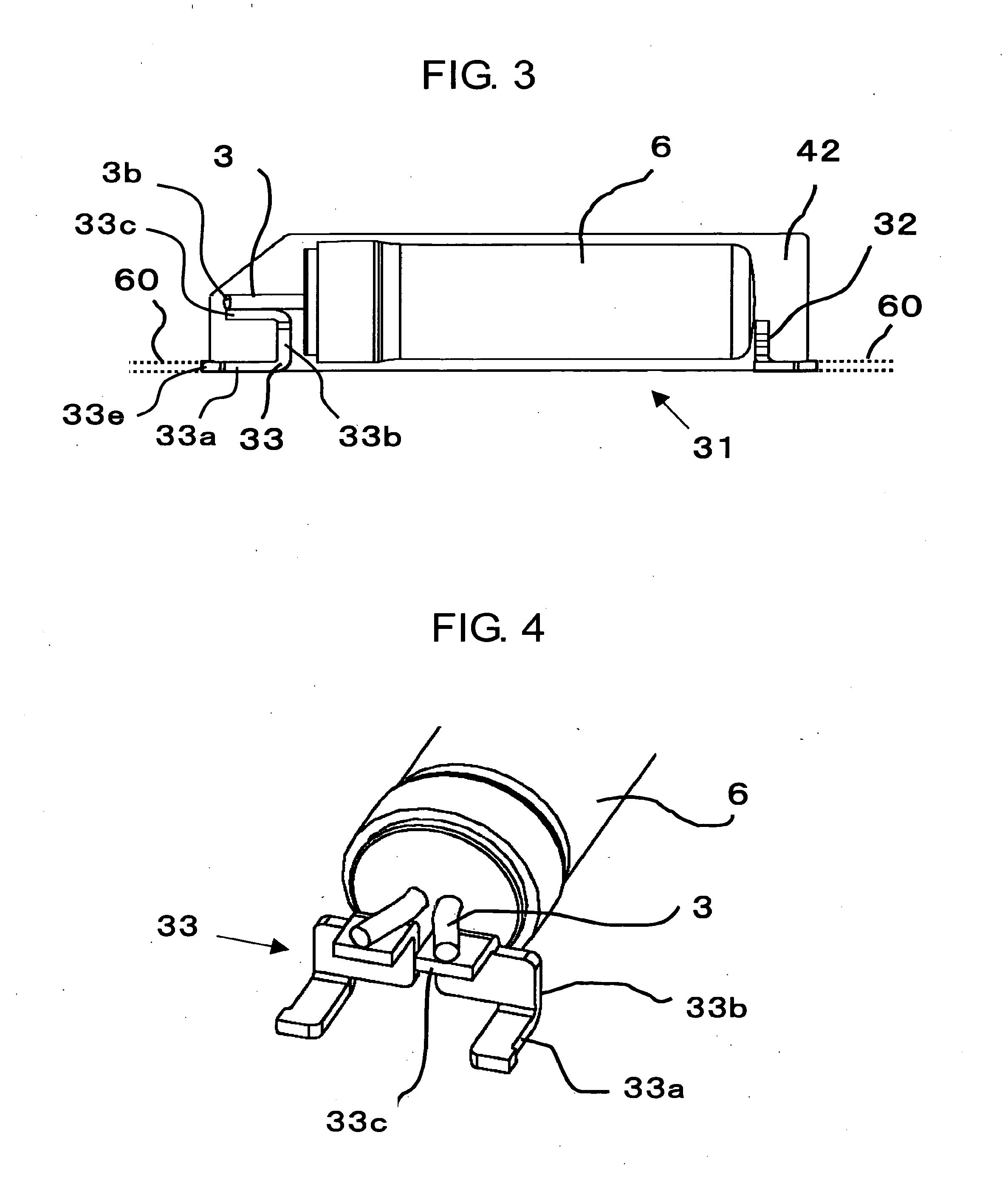
[0154]FIG. 2 is a schematic perspective view showing an appearance of the surface mount type piezoelectric vibrator related to the first embodiment. FIG. 3 is a schematic cross-sectional view of an inner part in a cross-sectional view of mold resin of the surface mount type piezoelectric vibrator related to the first embodiment. FIG. 4 is a schematic perspective view showing the electrode, terminal of the surface mount type piezoelectric vibrator related to the first embodiment. FIG. 5 is a schematic side view showing the electrode terminal shown in FIG. 4. FIG. 6 is a schematic side view showing the bonding process of the outer lead and electrode terminal.

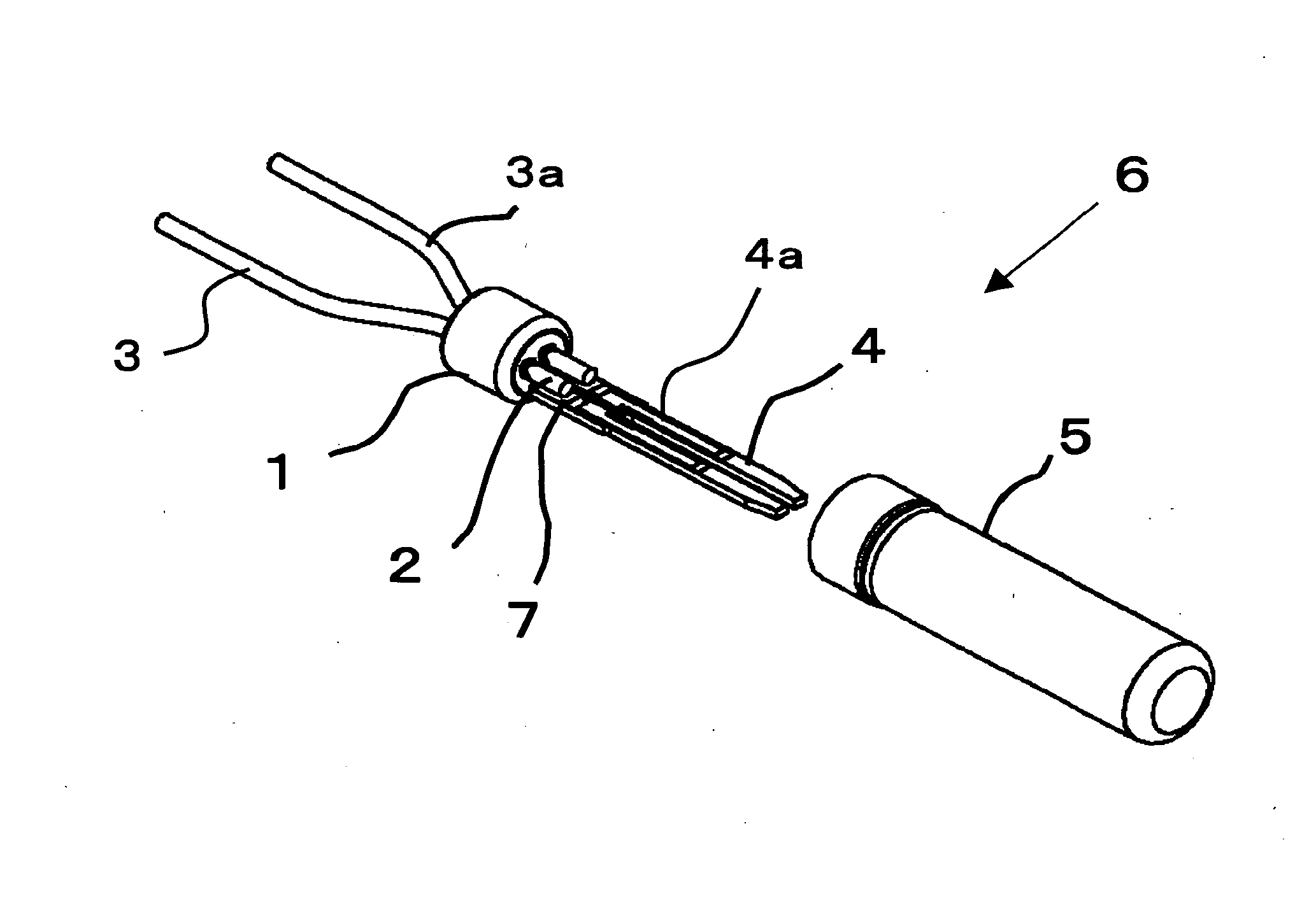
[0155] Since the cylinder-type package piezoelectric vibrator 6 has a cylindrical appearance, thereby not showing an unstable posture, it is difficult to mount the cylinder-type package piezoelectric v...

second embodiment

[0280] A second embodiment according to the invention will be described below with reference with FIG. 33. FIG. 33 is a schematic pattern diagram showing an example of the configuration of a tuning fork type quartz crystal oscillator according to a second embodiment of the invention. The tuning fork type quartz crystal oscillator 90 uses the surface mount type piezoelectric vibrator 31 described above as an oscillation piece and is connected to an integrated circuit.

[0281] In FIG. 33, a surface mount type piezoelectric vibrator 31 is set in a predetermined position on a substrate 92 and an integrated circuit for an oscillator indicated by a reference numeral 93 is provided adjacent to the surface mount type piezoelectric vibrator 31. An electronic part 94 such as a capacitor is also mounted. These parts are electrically connected together through a wiring pattern not shown. The mechanical vibration of the vibrating piece of the surface mount type piezoelectric vibrator 31 is conver...

third embodiment

[0283] A third embodiment of the present invention will be described below. The third embodiment is an example of an electronic unit using a surface mount type piezoelectric vibrator 31 produced by the method according to the present invention with the vibrator connected to a timing section. As an example of an electronic unit, a preferred embodiment of a portable information unit represented by a cell phone will be will be described below with reference to the drawings. FIG. 34 is a block diagram functionally showing the configuration of a portable information unit according to the embodiment.

[0284] A portable information unit 10 is a developed and improved version of a watch produced by means of related art. The portable information unit is similar to a watch in appearance. The portable information unit has a liquid crystal display, instead of an hour plate, which can display current time on a screen thereof. When the portable information unit is used as a communications unit, th...


PUM


Abstract

To provide a small-sized surface mount type piezoelectric vibrator with reduced mounting area, easy manufacturing, excellent reliability and quality, and low cost and a manufacturing method of the same. A surface mount type piezoelectric vibrator includes a piezoelectric vibrator having a piezoelectric vibrating piece bonded to an airtight terminal with a lead terminal and sealed by a cylindrical bottomed metal sealing tube, an electrode terminal connected to an external electrode to provide electrical continuity with the lead terminal, and mold resin for coating the piezoelectric vibrator, wherein a tip of the lead terminal to the lengthwise direction of the piezoelectric is arranged in almost the same position as a tip of a lower electrode formed parallel to a lower section.

Description

BACKGROUND OF THE INVENTION [0001] 1. Field of the Invention [0002] The present invention relates to a surface mount type piezoelectric vibrator molding a periphery of a piezoelectric vibrator with a resin and a method for manufacturing the same, an oscillator, electronic unit and wave clock having the surface mount type piezoelectric vibrator. [0003] 2. Description of the Related Art [0004] Piezoelectric vibrators are indispensable to the production of industrial products such as clocks, oscillators and electronic units, and used as time keeping sources, timing sources or reference sources for signals. A cylinder-type package is commonly used as a piezoelectric vibrator package. [0005] However, since the cylinder-type package piezoelectric vibrator is cylindrical, the position thereof unstable or two elongate lead terminals are bendable, so that unlike other electronic parts, the cylinder-type package piezoelectric vibrator cannot be, as it is, surface-mounted using an automatic mo...

Claims


Application Information

Patent Timeline
IPC IPC(8): H01L41/00H01L41/09H01L41/18H01L41/22H01L41/23H01L41/29H03H3/02H03H9/02
CPCH03H3/02H03H9/0519
Inventor SATO, MASAYUKIKAMIYAMA, ATSUSHIOKU, SADAO
Owner SII CRYSTAL TECH
Why Eureka
Try Eureka