
Q-point stabilization for linear interferometric sensors using tunable diffraction grating

Inactive Publication Date: 2005-10-20
VIRGINIA TECH INTPROP INC
View PDF3 Cites 30 Cited by
  • Summary
  • Abstract
  • Description
  • Claims
  • Application Information

AI Technical Summary

Problems solved by technology

Intensity-based sensors are typically processed by detecting an intensity of light transmitted by, or attenuated by, the sensor as a function of a fluctuating measurand (e.g., pressure, temperature, etc.) The systems for processing the output of such sensors are relatively uncomplicated; however, they are sensitive to signal fading due to perturbations in operating parameters other than the measurand.
The processing systems for interferometric sensors, which must count these fringes, are typically more complex, and therefore more costly and slow, than the processing systems for intensity-based sensors.
These systems are also subject to fringe direction ambiguity (i.e., a change in direction of the measurand at a peak or trough of a fringe may not be detected).
However, interferometric sensor systems involving fringe counting are not as sensitive to non-measurand operating parameter drifts as intensity-based sensors.
Unfortunately, maintaining the Q-point in the optimal location is difficult.
Assembling the sensor to fix the Q-Point in the optimal location requires assembly tolerances on the order of nanometers, which is very difficult.
In addition, changes in the physical dimensions of the sensor due to thermal expansion or contraction resulting from temperature changes will cause a drift in the Q-Point from the optimal location.
The servo system method is straightforward and good for high-frequency signal measurements, but the reference constant voltage may not be constant because of temperature drift, static bias change and source power fluctuation.
Adjusting the operating point by changing the bias current of a laser diode may cause optical power fluctuation and is sensitive to back-reflections.
This technique is also subject to laser mode hopping and high cost.
However, it is possible that neither of the two quadrature channels operates at the optimal Q-point at a certain time, provided that a 90 degree phase shift can be maintained during the measurement, which is as hard to control as the operating point itself.
Its major disadvantage is that it is not suitable for real time detection of a broadband signal, such as an acoustic wave or a high frequency pressure, because a large amount of time is required to process the large amount of data from the CCD array.
Another disadvantage of the spectrum detection is the high cost, especially for sensors operating at NIR wavelengths, where an expensive detector array must be used.

Method used


Image

  • Q-point stabilization for linear interferometric sensors using tunable diffraction grating
  • Q-point stabilization for linear interferometric sensors using tunable diffraction grating
  • Q-point stabilization for linear interferometric sensors using tunable diffraction grating

Examples


Embodiment Construction

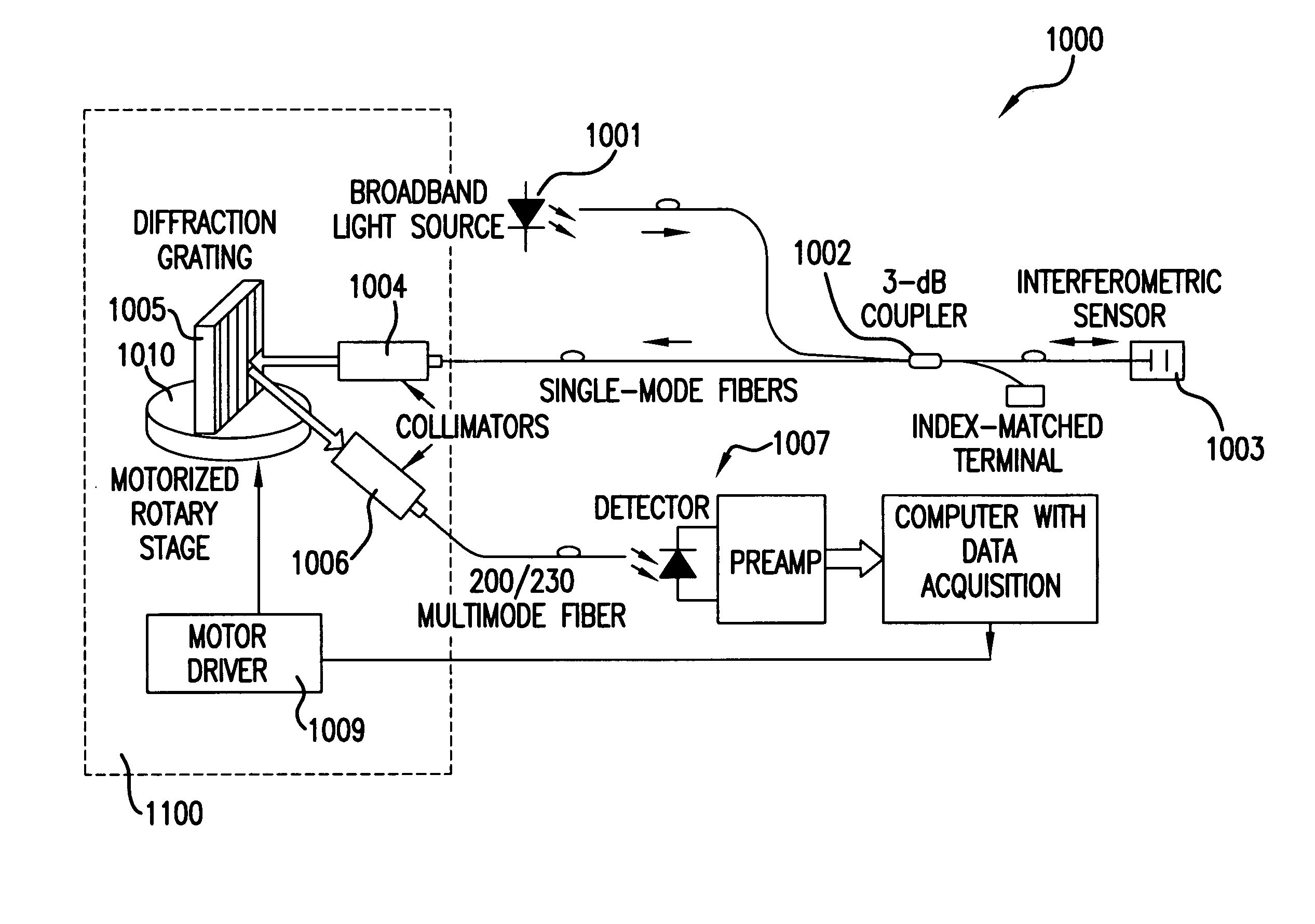
[0026] The present invention will be discussed with reference to preferred embodiments of linear interferometric sensor systems. Specific details are set forth in order to provide a thorough understanding of the present invention. The preferred embodiments discussed herein should not be understood to limit the invention. Furthermore, for ease of understanding, certain method steps are delineated as separate steps; however, these steps should not be construed as necessarily distinct nor order dependent in their performance.

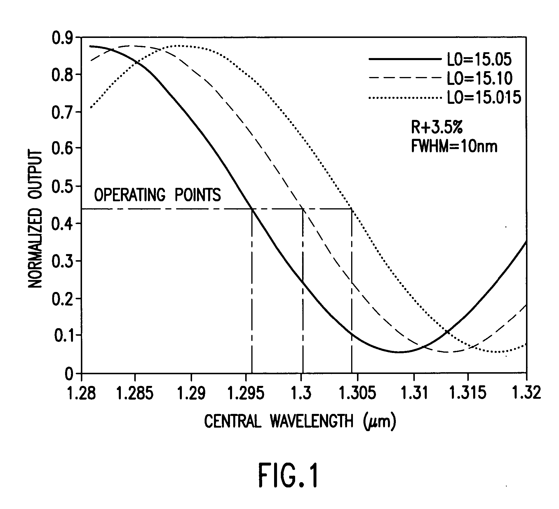
[0027] Interferometric-intensity-based detection is a widely used demodulation technique in optical interferometric sensors, such as Fabry-Perot, Mach-Zehnder and Sagnac sensors. When a monochromatic light of wavelength λ is used to interrogate the sensors, the optical intensity of the interference between the sensing beam and the reference beam can be expressed as:

I=I1I2+2{square root}{square root over (I1I2 cos φ)}

where I1 and I2 represent the optical intensit...


PUM


Abstract

A linear interferometric sensor system in which the light output from the interferometric sensor is optically bandpass filtered before conversion to an electrical signal by an adjustable diffraction grating and the center wavelength of the adjustable diffraction grating is controlled by a feedback circuit responsive to the steady state component of the electrical signal corresponding to the filtered sensor return. The adjustable may comprise a diffraction grating a diffraction grating mounted on a motor driven rotary stage. The invention is particularly useful in self calibrating interferometric / intensity-based sensor configuration, but is also applicable in a wide variety of linear interferometric sensor configurations.

Description

[0001] This invention was partially made with Government support under grant number DE-FC3601GO11050 awarded by the U.S. Department of Energy. The Government may have certain rights in the invention.BACKGROUND OF THE INVENTION [0002] 1. Field of the Invention [0003] The invention relates to optical sensors generally, and more particularly to linear interferometric optic sensors. [0004] 2. Discussion of the Background [0005] Optical sensors (fiber optic or otherwise) may be either intensity based or interferometric. Intensity-based sensors are typically processed by detecting an intensity of light transmitted by, or attenuated by, the sensor as a function of a fluctuating measurand (e.g., pressure, temperature, etc.) The systems for processing the output of such sensors are relatively uncomplicated; however, they are sensitive to signal fading due to perturbations in operating parameters other than the measurand. Examples of intensity-based sensors include the pressure-induced long p...

Claims


Application Information

Patent Timeline
IPC IPC(8): G01B9/02
CPCG01B9/02007G01B9/02041G01B2290/25G01B9/02023G01B9/02067
Inventor WANG, ANBOYU, BING
Owner VIRGINIA TECH INTPROP INC
Learn More