Semiconductor laser

a laser and semiconductor technology, applied in the direction of semiconductor laser structure details, semiconductor lasers, semiconductor laser arrangements, etc., can solve the problems of reduced injecting current, noise and jitter, and disadvantaged light output, so as to increase the threshold current and reduce the cod

Active Publication Date: 2005-10-20
PANASONIC SEMICON SOLUTIONS CO LTD
View PDF1 Cites 8 Cited by
  • Summary
  • Abstract
  • Description
  • Claims
  • Application Information

AI Technical Summary

Benefits of technology

[0024] According to this structure, it is possible to avoid both an increase in the threshold current arising when the section having the larger energy bandgap is too small in compariso

Problems solved by technology

This is because the laser beam is difficult to condense at small horizontal divergence angles θ∥, and, as a result, a desirable coupling coefficient cannot be obtained in optical coupling with the address pits on optical disk media, leading to noise and jitter.
It is widely known that generally the shape of the ridge, in a cross-section orthogonal to the lengthwise direction of the resonator, is a trapezoid whose upper base is shorter than the lower base, and that while a laser beam having a larger horizontal divergence angle θ∥ is obtained for shorter lower base widths, light output increases are disadvantaged because of the region for injecting current being reduced and device resistance increased for shorter lower base widths.
However, because of the balancing, in this conventio

Method used


Image

  • Semiconductor laser
  • Semiconductor laser
  • Semiconductor laser

Examples


Embodiment Construction

[0042] A semiconductor laser pertaining to a preferred embodiment of the present invention is described below while referring to the diagrams.

Structure

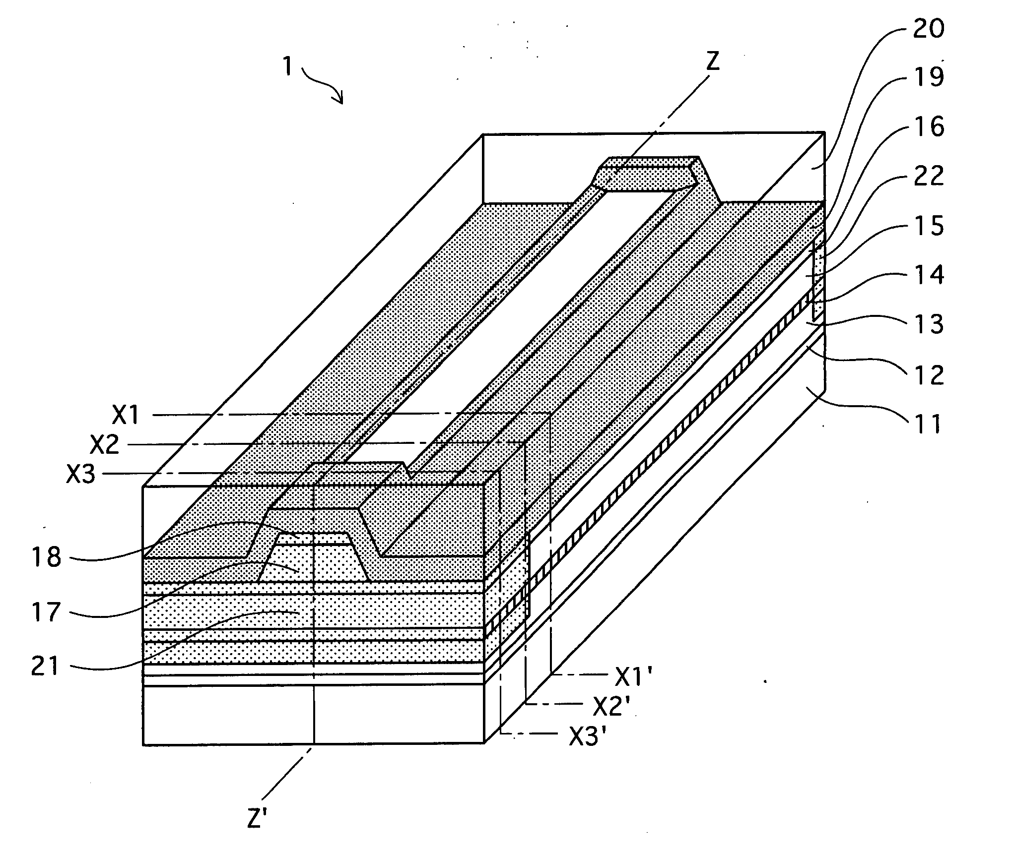
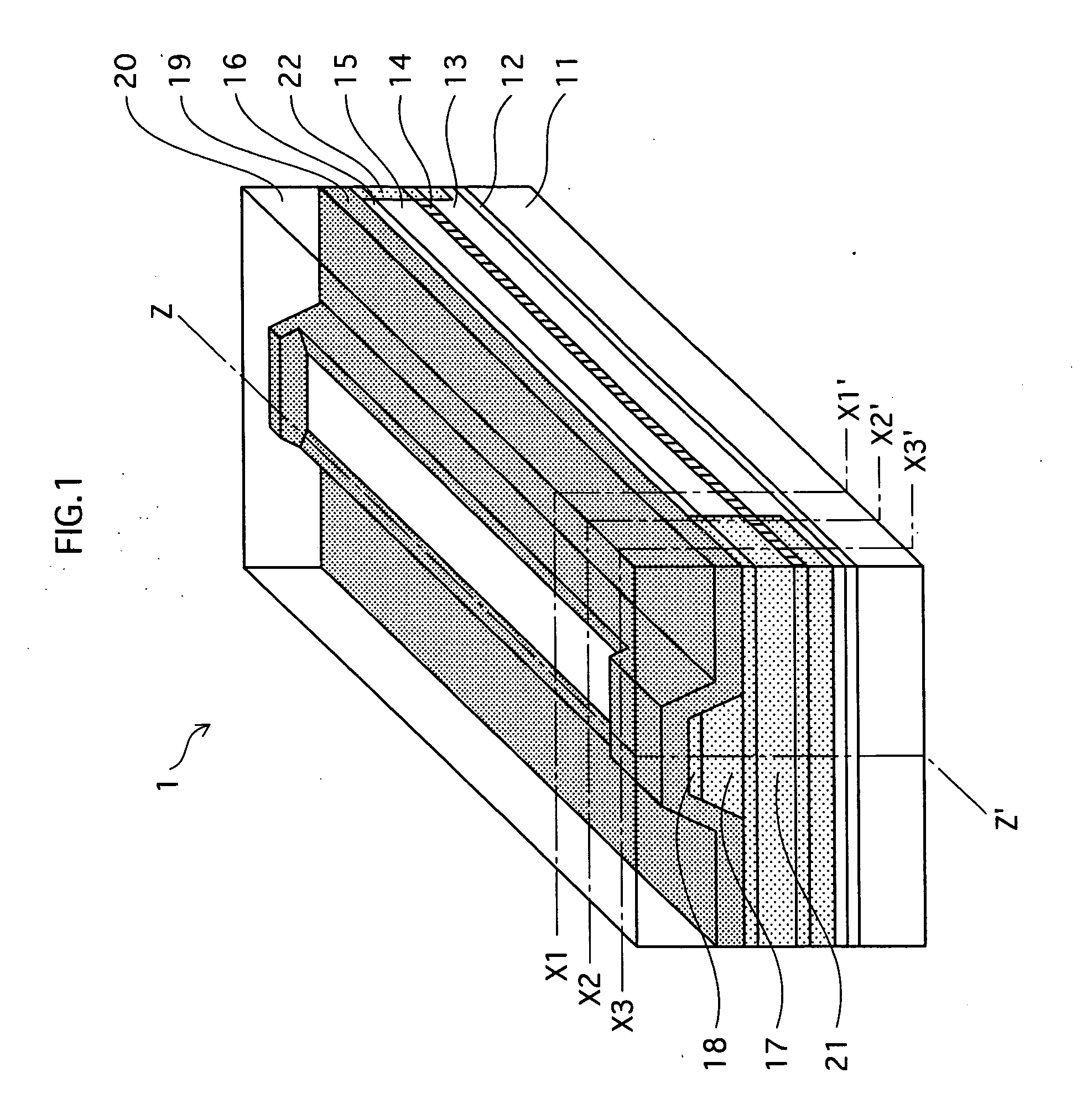
[0043]FIG. 1 is a perspective view showing a semiconductor laser 1.

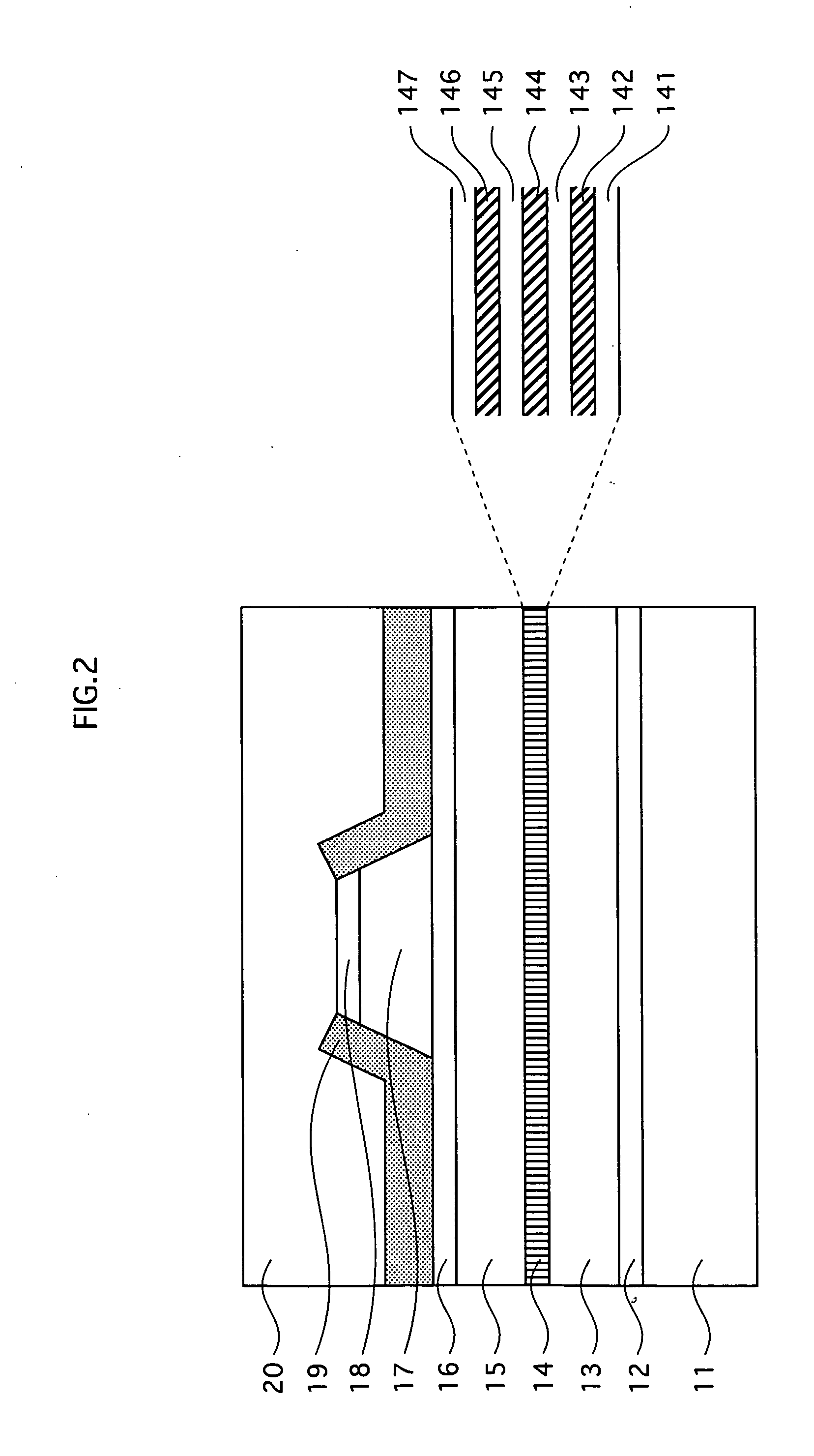
[0044] Semiconductor laser 1 is formed from an n-type semiconductor substrate 11, an n-type buffer layer 12, an n-type cladding layer 13, a quantum-well active layer 14, a p-type 1st cladding layer 15, an etch stop layer 16, a p-type 2nd cladding layer 17, a p-type cap layer 18, a current blocking layer 19, and a p-type contact layer 20 layered in the stated order. P-type contact layer 20 is depicted as being transparent for ease of viewing.

[0045] The layers from n-type cladding layer 13 to p-type 2nd cladding layer 17 structure an optical waveguide, and a reflective film (not depicted) is coated on a light-emission end surface (near end in FIG. 1) and the end surface opposite the light-emission end surface to thus structure an optical resonator.

[0046] The reflec...


PUM


Abstract

In a semiconductor laser 1, a current blocking layer 19 covers a p-type 2nd cladding layer 17 and a p-type cap layer 18 that extend in a lengthwise direction of an optical resonator, at both a light-emission end and an end opposite the light-emission end, to thus form non-current injection regions in an optical waveguide. By making current blocking layer 19 at the light-emission end large enough that carriers flowing from a current injection region do not reach the light-emission end surface, the light intensity distribution in the near field at the light-emission end surface is strongly concentrated, allowing the horizontal divergence angle of an emerging laser beam to be enlarged. This structure makes it possible to enlarge the horizontal divergence angle independently after having optimized the thickness of cladding layers and the size of the current injection region.

Description

BACKGROUND OF THE INVENTION [0001] 1. Field of the Invention [0002] The present invention relates to semiconductor lasers, and in particular to technology that allows the horizontal divergence angle to be enlarged independently of increases in laser beam output. [0003] 2. Related Art [0004] Optical disks such CD (compact disk) and DVD (digital versatile disk) have become widely used in recent years. The demand for recordable optical disk devices is rapidly expanding due to the wide acceptance in consumer use of optical disks as media suitable for recording mass digital information typified by AV (audio visual) contents. [0005] The recording speed of optical disk devices is improved by increasing the light output of semiconductor lasers used in optical pickups. Improving the writing speed furthers the convenience of users and provides a major selling point for products. [0006] This has led to mounting demands for light output increases in 780-nm AlGaAs semiconductor lasers used in op...

Claims


Application Information

Patent Timeline
IPC IPC(8): H01S5/227H01S5/00H01S5/02H01S5/10H01S5/16H01S5/20H01S5/22H01S5/223H01S5/343H01S5/40
CPCB82Y20/00H01S5/1039H01S5/162H01S5/168H01S2301/18H01S5/2231H01S5/34333H01S5/4031H01S5/4087H01S5/2214
Inventor UEDA, TETSUOKUME, MASAHIROKAWATA, TOSHIYAKIDOGUCHI, ISAO
Owner PANASONIC SEMICON SOLUTIONS CO LTD
Why Eureka
Try Eureka