Image reject filtering in a direct sampling mixer

a direct sampling mixer and image filter technology, applied in the direction of multiple-port networks, electrical equipment, switch capacitor networks, etc., can solve the problems of difficult to realize the precise matching of quadrature signal components, the need to suppress or reject image signals, and the many challenges of radio frequency (rf) devices integrated on a single chip, etc., to achieve the effect of reducing device power requirements, chip area, and cos

Inactive Publication Date: 2005-10-20
TEXAS INSTR INC
View PDF3 Cites 61 Cited by
  • Summary
  • Abstract
  • Description
  • Claims
  • Application Information

AI Technical Summary

Benefits of technology

[0017] The invention provides technical advantages including but not limited to a reduction in dynamic range requirements of downstream circuitry, such as for example IF amplifiers, and reduction in device power requirements, chip area, and cost. These and other features, advantages, and benefits of the present invention will become apparent to one of ordinary skill in the art upon careful consideration of the detailed description of representative embodiments of the invention in connection with the accompanying drawings.

Problems solved by technology

Efforts to provide intermediate frequency (IF) and radio frequency (RF) devices integrated on a single chip face many challenges.
One problem in particular is the need to suppress or reject image signals by providing band-pass filtering in transceiver devices designed for portable wireless applications.
Precise matching of quadrature signal components is difficult to realize, however, particularly at higher frequencies.
Single and multistage RC networks may be used in some situations, but are generally susceptible to RC mismatch, are limited to narrow-band applications, and are increasingly difficult to implement for higher frequency applications.
The switched capacitor filters known in the arts, however, are relatively inefficient in terms of power consumption and area requirements.
Larger area requirements generally also lead to increased costs.
This type of switched capacitor network encounters the same problems of power consumption and cost as other switched capacitor networks, due in large part to its reliance on the use of op amps.
Such an approach has been limited to real filtering however.

Method used


Image

  • Image reject filtering in a direct sampling mixer
  • Image reject filtering in a direct sampling mixer
  • Image reject filtering in a direct sampling mixer

Examples


Embodiment Construction

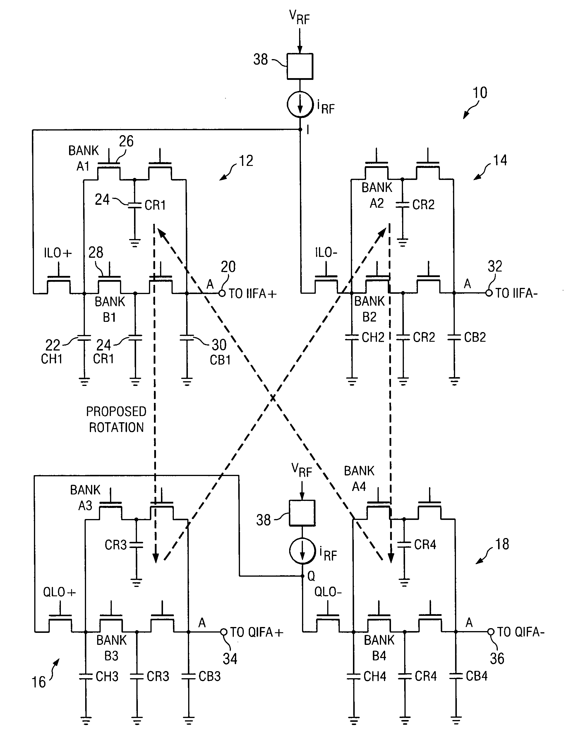
[0026] In general, the preferred embodiments of the invention provide band-pass and image reject filtering in a direct sampling mixer of an IF or RF system. This is accomplished by the use of rotating capacitors among the in-phase I and quadrature Q branches of the system, denoted I+, I−, Q+, Q−, respectively. The exchange of information among the branches of the I and Q channels enables the implementation of a complex filter. It should be appreciated that preferred embodiments of the invention may be implemented without the use of op amps.

[0027] Referring primarily to FIG. 1, the methods of the invention are portrayed in a block diagram in which it can be seen that rotation of a switched capacitor CR between the I and Q channels of the circuit causes a sharing of the charge among the four paths, I+, I−, Q+, Q−, resulting in a direct sampling and a complex filtering arrangement 10. The preferred embodiment of the filter 10 shown can be seen to have four sub-circuits 12, 14, 16, 18,...


PUM


Abstract

Disclosed are methods, circuits and systems for image reject filtering in a multi-tap direct sampling mixer (MTDSM) of an IF or RF system. Disclosed is the use of rotating capacitors among the in-phase and quadrature branches of a signal processing system. The exchange of information among the branches of the I and Q channels is used in the implementation of a complex filter. Embodiments using cascaded multiple stages of the complex filter to provide higher order complex filters are also disclosed.

Description

RELATED APPLICATIONS [0001] This application is related to patent application, Ser. No. ______ (attorney docket number TI-34776), which is incorporated herein in its entirety for all purposes by this reference.TECHNICAL FIELD [0002] The invention relates to signal processing circuits and methods. More particularly, the invention relates to methods and circuits for image reject filtering in a direct sampling mixer. BACKGROUND OF THE INVENTION [0003] Integrated radio transmitters and receivers have become increasingly popular. Efforts to provide intermediate frequency (IF) and radio frequency (RF) devices integrated on a single chip face many challenges. One problem in particular is the need to suppress or reject image signals by providing band-pass filtering in transceiver devices designed for portable wireless applications. Such applications require low power consumption, low silicon area, low external component count and a high degree of single-chip integration. [0004] Quadrature s...

Claims


Application Information

Patent Timeline
Patent Type & Authority Applications(United States)
IPC IPC(8): H03D7/18H03H19/00H04B1/16H04B1/28
CPCH03D7/18H03H2007/0192H03H19/004
Inventor MUHAMMAD, KHURRAMSTASZEWSKI, ROBERT B.LEIPOLD, DIRK
Owner TEXAS INSTR INC
Why Eureka
Try Eureka