Process for recovering rare gases using gas-recovering container

Active Publication Date: 2005-10-27
TAIYO NIPPON SANSO CORP
View PDF13 Cites 38 Cited by
  • Summary
  • Abstract
  • Description
  • Claims
  • Application Information

AI Technical Summary

Benefits of technology

[0027] According to the process for recovering a rare gas by the present invention, it is possible to carry out separating and purifying treatment by introducing rare gas -containing exhaust gas in a stable state to the rare gas separation and purifying equipment even if the total amount or the rare gas concentration of rare gas-containing exhaust gas discharged from an equipment using a rare gas. Further, the process can treat rare gas containing exhaust gases discharged from a plurality of equipments using the rare gas inclusively, so

Problems solved by technology

Krypton and xenon are very expensive gases because of their present proportion in the atmosphere and complicated separation processes.
On this account, the recovery container needs to be changed frequently and consequently, the increase of the distribution cost of the recovery container will be caused.
Further, there is a problem such that the control of a rare gas separation and purifying apparatus will be difficult because the rare gas concentration varies and the rare gas concentration is different in each of recovery containers.
Consequently, the cost for measuring is added or the size of the

Method used


Image

  • Process for recovering rare gases using gas-recovering container
  • Process for recovering rare gases using gas-recovering container
  • Process for recovering rare gases using gas-recovering container

Examples


example 1

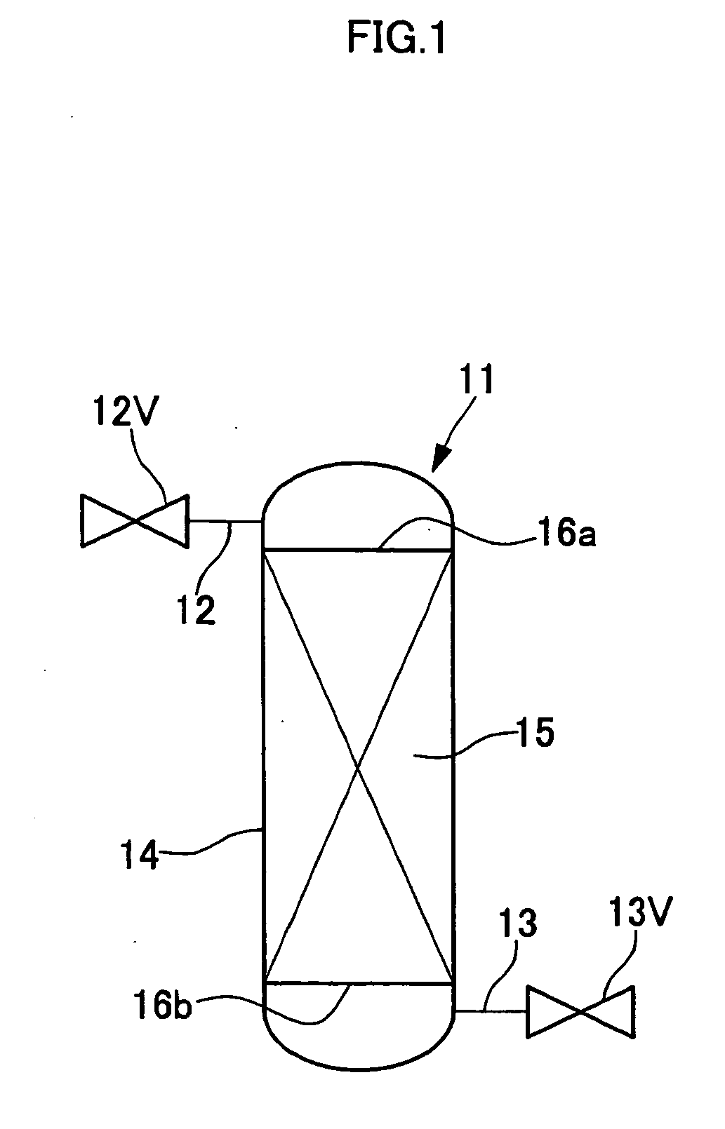
[0092] As shown in FIG. 1, the adsorption amount of xenon was measured using a gas-recovering container 11, which comprises an 8 L internal volume air-tight container 14 containing 4.0 Kg of activated carbon 15 therein. At first, in order to purge atmospheric components in the gas-recovering container 11, argon was introduced at a rate of 1 L / minute from one joint section 12 and simultaneously pumping was carried out from the other joint section 13 while heating at 300° C. by winding a heater on the circumference of the gas-recovering container 11. This condition was continued for 12 hours and thereafter, the valve 12 was closed to stop the argon introduction, and pumping was carried out until the pressure in the gas-recovering container 11 reached 100 Pa. Then, heating of the gas-recovering container 11 was stopped and it was cooled to 25° C.

[0093] Into this gas-recovering container 11, a mixed gas of 50% of xenon and 50% of argon was introduced and the total introduction amount a...

example 2

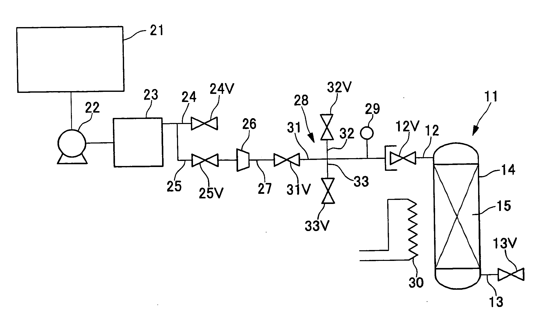
[0094] To a gas recovery apparatus as shown in FIG. 2, the gas-recovering container 11 was connected and the rare gas recovery amount was measured. The gas-recovering container 11 used was comprised of a 47 L internal volume air-tight container 14 containing 20 Kg of activated carbon 15 filled therein. The gas-recovering container 11 was subjected to purge procedure in the same manner as in Example 1.

[0095] To an equipment using a rare gas 21, xenon was introduced at a flow rate of 1 L / minute to generate plasma and also pumping was carried out in a vacuum pumping apparatus 22. In this procedure, argon was introduced at a rate of 1 L / minute as a purge gas for the vacuum pumping apparatus 22 and argon was introduced at a rate of 0.5 L / minute as a purge gas for a harmful component removal means 23. Therefore, in a compressor 26, argon, pressurization was conducted using argon having a xenon proportion of 40% at a rate of 2.5 L / minute.

[0096] While the gas pressurized in the compressor...

example 3

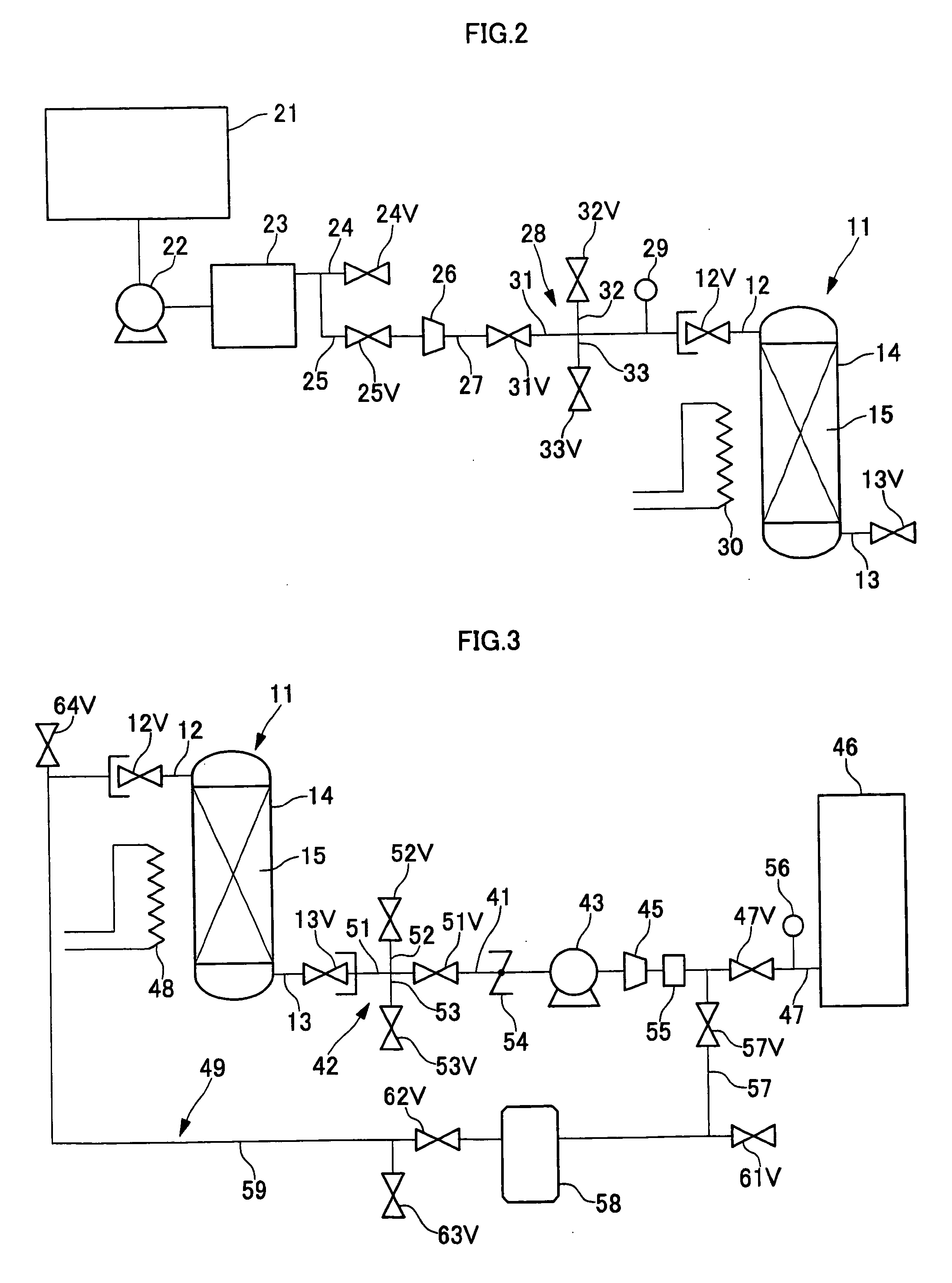
[0098] To a gas discharge apparatus as shown in FIG. 3, the gas-recovering container 11, which recovered 1250 L of xenon in Example 2, was connected and the amount of xenon discharged was measured. As a vacuum pumping apparatus 43, which is gas discharge means, a vacuum pump having an pumping speed of 1000 m3 / hour at 100 Pa was used and as a compressor 45, one capable of outputting a gas at a rate of 40 L / minute when the pressure was increased from atmospheric pressure to 0.8 MPa was used. As a rare gas concentration measurement apparatus 55, a thermo-conductivity method was used.

[0099] While the gas-recovering container 11 was heated at 300° C., the gas was led out from the gas-recovering container 11, and the xenon concentration of this gas was measured. As a result, xenon was not detected for 10 minutes after the starting of discharging the gas and the xenon concentration was about 20% after the passage of 10 minutes. Thereafter, the xenon concentration was increased to the maxi...


PUM


Abstract

A process comprises the steps of recovering exhaust gas containing krypton or xenon which are used as an atmospheric gas for semiconductor product preparation apparatuses; introducing the exhaust gas to separating and purifying equipment and thereby separating and purifying krypton or xenon from the exhaust gas, wherein the former step of recovering a rare gas-containing exhaust gas discharged from an equipment using a rare gas comprises removing one or more interfering gases which lower(s) the adsorption ability of activated carbon capable of adsorbing rare gases; and thereafter pressure filling the rare gas-containing exhaust gas obtained after said one or more interfering gases removal treatment into a gas-recovering container, which comprises a air-tight container having a joint section capable of connecting a gas duct through an on-off valve and containing therein the activated carbon capable of adsorbing rare gases; and thereby recovering the rare gas containing exhaust gas; and the latter step of introducing the recovered rare gas-containing exhaust gas in the gas-recovering container to rare gas separating and purifying equipment comprises desorbing the rare gas adsorbed on the above activated carbon by reducing the pressure of the inside of the above gas-recovering container; and discharging the rare gases desorbed from the gas-recovering container and introducing to the above rare gas separation and purifying equipment.

Description

TECHNICAL FIELD [0001] The present invention relates to a process for recovering rare gases using a gas-recovering container, more particularly relates to a process of recovering a rare gas in a rare gas-containing exhaust gas discharged from an equipment using said rare gas, and introducing the recovered rare gas-containing exhaust gas into rare gas separation and purifying equipment and therein separating and purifying the rare gas. [0002] The rare gas in the present invention is krypton or xenon, or a mixed gas thereof. TECHNICAL BACKGROUND [0003] In processes for producing semiconductor integrated circuits, liquid crystal panels, solar batteries and panels thereof, and semiconductor products such as magnetic disks and the like, apparatuses capable of generating plasma in an atmosphere of an inert gas and carrying out various treatments of semiconductor products by the plasma have been widely used. [0004] Conventionally, in these treatments, argon gas has been used as an inert ga...

Claims


Application Information

Patent Timeline
IPC IPC(8): B01D53/02B01D53/68B01D53/46B01D53/56B01D53/58B01D53/62B01D53/70B01D53/81C01B23/00
CPCB01D53/02B01D2258/0216B01D2257/11B01D2253/102F16H55/171F02B67/06B23P15/14
Inventor ISHIHARA, YOSHIO
Owner TAIYO NIPPON SANSO CORP
Why Eureka
Try Eureka