Scanning probe microscope probe with integrated capillary channel

Inactive Publication Date: 2005-10-27
THE BOARD OF TRUSTEES OF THE UNIV OF ILLINOIS
View PDF2 Cites 71 Cited by
  • Summary
  • Abstract
  • Description
  • Claims
  • Application Information

AI Technical Summary

Problems solved by technology

Needless to say, the SPM probe's cantilever beam with integrated tip is a performance limiting device in the overall scanning probe microscope system.
There are a number of major drawbacks to existing fabrication methods.
However, microcontact printing invariably requires a dedicated photolithography mask to produce inverse mold features

Method used


Image

  • Scanning probe microscope probe with integrated capillary channel
  • Scanning probe microscope probe with integrated capillary channel
  • Scanning probe microscope probe with integrated capillary channel

Examples


Embodiment Construction

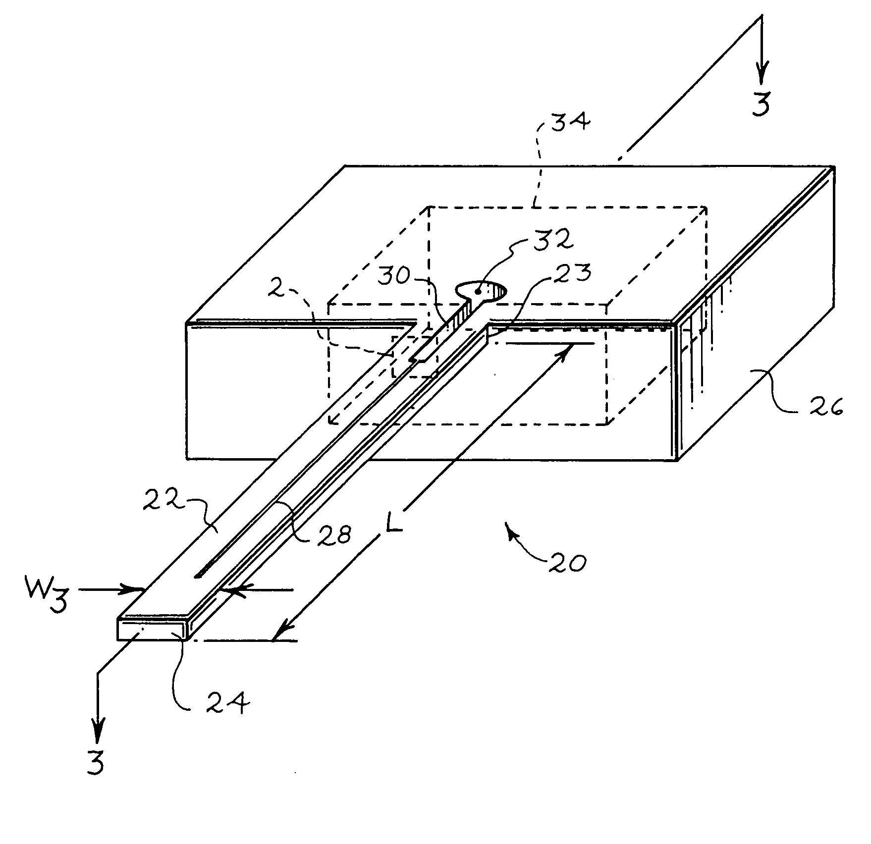
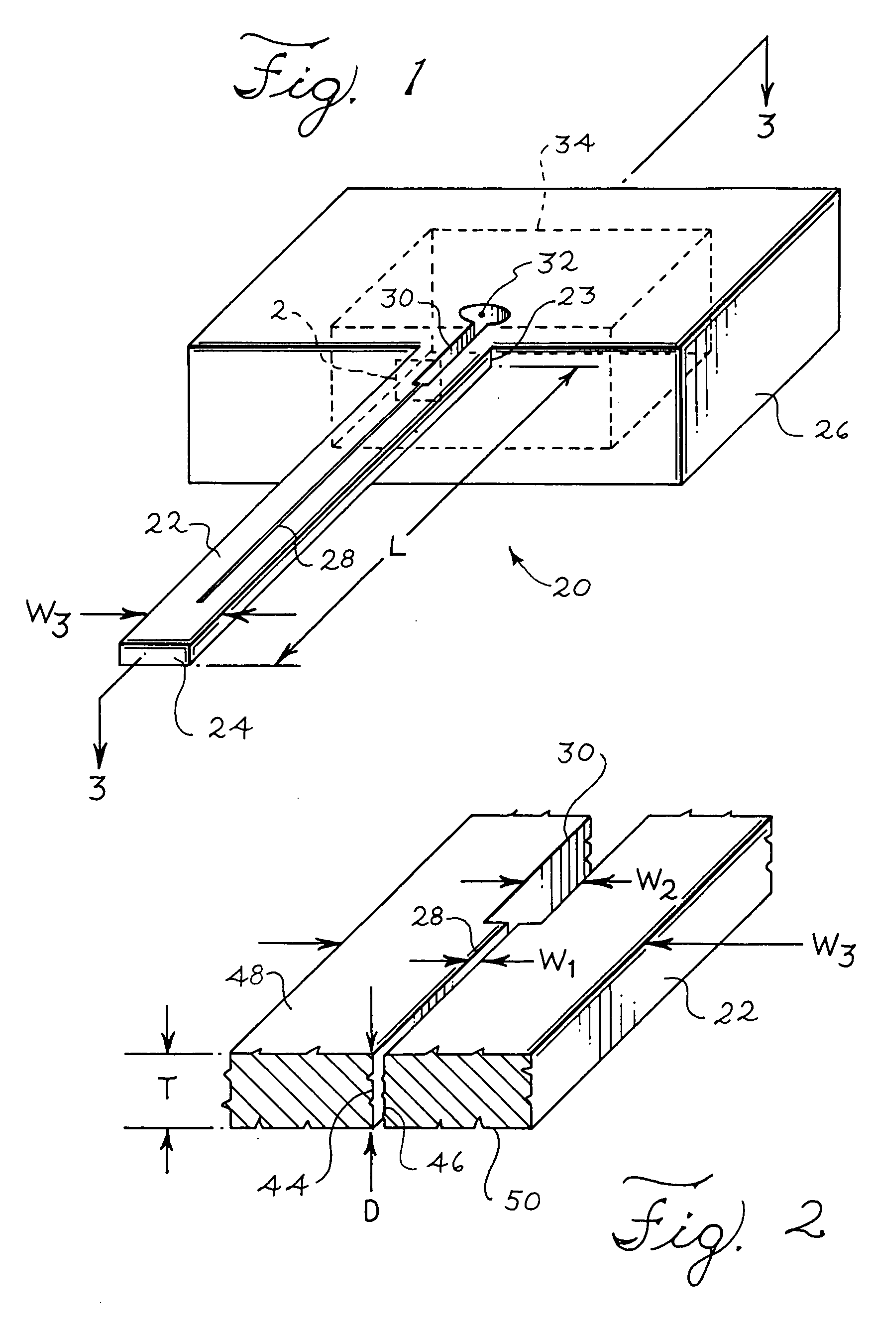
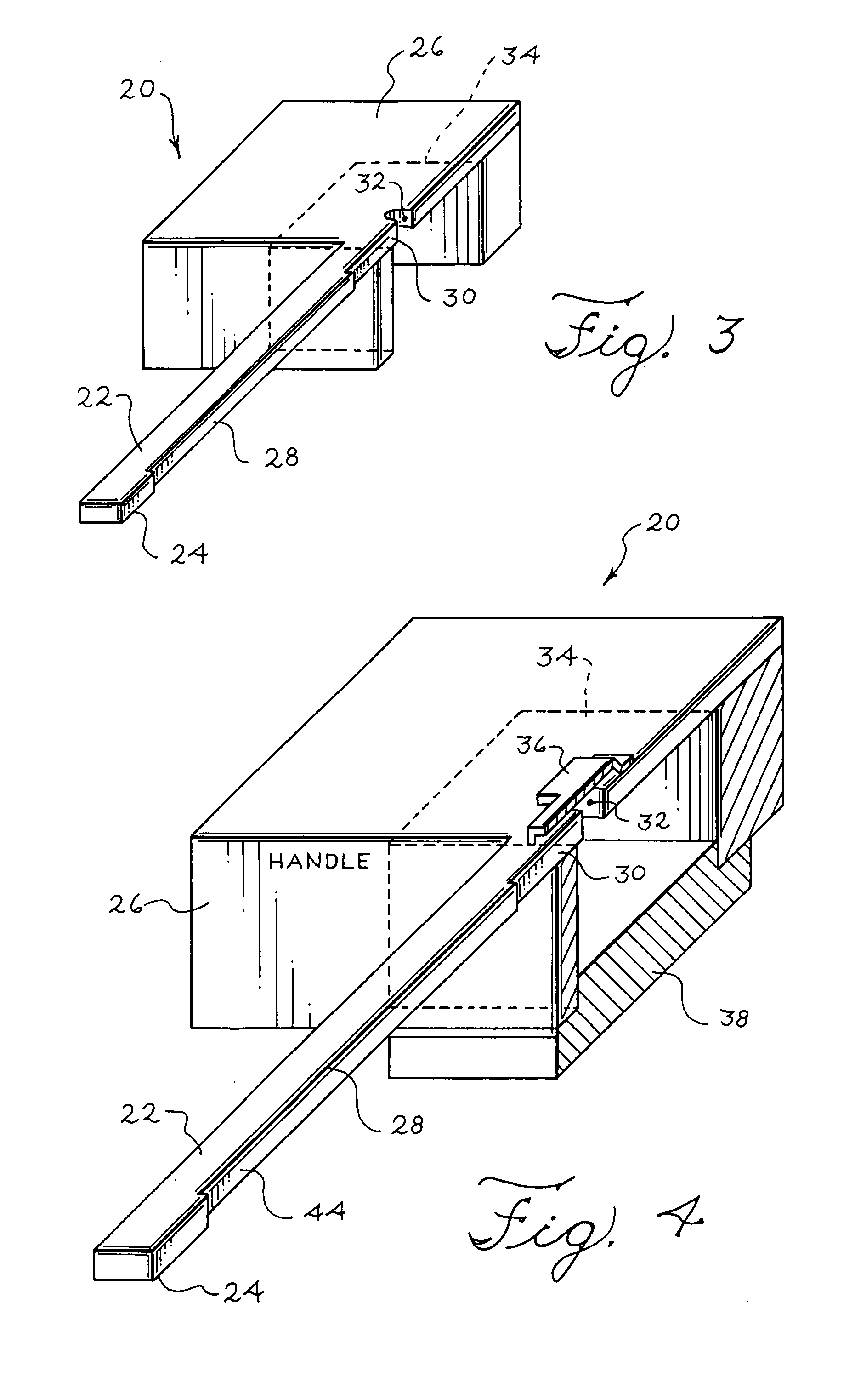
[0022] The present invention describes a scanning probe microscope (SPM) probe with a capillary channel and a method for fabricating the same. The SPM probe includes a handle and a cantilever shank connected with the handle, wherein a capillary channel is formed in the cantilever shank. In one embodiment, the capillary channel has a width W1 from 1 nanometer to 50 nanometers. In one embodiment, the capillary channel is formed in the cantilever shank using focused ion beam etching. The capillary channel allows for ink to travel from a reservoir in the handle to a tip at one end of the cantilever shank, supplying ink to the tip and eliminating the need to re-ink the tip by dipping the tip in a well. Additionally, by forming a capillary channel, instead of a traditional tunnel, the structure of the SPM probe is simplified, and the cantilever shank can retain its flexibility.

[0023] Shown in FIGS. 1-11 are views of SPM probes suitable for use in a scanning probe microscope. Please note ...


PUM


Abstract

A scanning probe microscope probe is disclosed. The scanning probe microscope probe includes a handle and a cantilever shank connected with the handle. The cantilever shank has at one end a base connected with the handle and at an opposing end a tip. The cantilever shank forms a capillary channel between the base to the tip of the cantilever shank.

Description

FEDERALLY SPONSORED RESEARCH OR DEVELOPMENT [0001] This invention was made with Government support under Contract Number NW 0650 300F245 awarded by the Defense Advanced Research Projects Agency (DARPA). The Government has certain rights in the invention.BACKGROUND [0002] This invention relates generally to scanning probe microscope (hereinafter “SPM”) probes for use in scanning probe microscopy, and in particular, to an SPM probe formed with an integrated capillary and to a method of manufacturing the same. [0003] A scanning probe microscope is an important instrument for science and technology. One of the first scanning probe microscopes ever developed was called a Scanning Tunneling Microscope (STM). Another device within the scanning probe microscope family is an Atomic Force Microscope (hereinafter “AFM”). Nowadays, scanning probe microscopes are used to measure surface properties with atomic resolution. For example, scanning probe microscopes can be used to observe the structur...

Claims


Application Information

Patent Timeline
IPC IPC(8): B82B3/00G01Q70/16G03F7/00
CPCB82B3/00B82Y10/00B82Y35/00B82Y40/00G03F7/0002G01Q70/10B82Y30/00G01Q70/16
Inventor LIU, CHANG
Owner THE BOARD OF TRUSTEES OF THE UNIV OF ILLINOIS
Why Eureka
Try Eureka