Charged particle beam adjusting method and charged particle beam apparatus

a technology of charged particle beam and charge particle, which is applied in the direction of optical radiation measurement, beam deviation/focusing by electric/magnetic means, instruments, etc., to achieve the effect of speeding up processing speed and high accuracy

Inactive Publication Date: 2005-10-27
HITACHI HIGH-TECH CORP
View PDF9 Cites 21 Cited by
  • Summary
  • Abstract
  • Description
  • Claims
  • Application Information

AI Technical Summary

Benefits of technology

[0006] Firstly, according to the present invention, to accomplish the above object, a charged particle beam apparatus is provided which comprises a charged particle beam source, an objective lens for focusing a charged particle beam emitted from the charged particle beam source to irradiate it on a specimen, a detector for detecting charged particles emitted from the specimen, a deflector for deflecting the charged particle beam to a region which is out of axis of the objective lens to thereby tilt the charged particle beam in relation to an optical axis of the objective lens, a stigmator for correcting an astigmatic aberration of the charged particle beam, and a controller for automatically controlling the stigmator, objective lens and deflector such that when the charged particle beam is tilted, astigmatism correction and focus adjustment of the charged particle beam and FOV shift correction are conducted on the basis of the charged particles detected by the detector, wherein the controller includes selection means for inhibiting at least one of the astigmatism correction, focus adjustment and FOV shift correction from being carried out. According to the first construction, when the beam is tilted, an operator can set a correction condition at will in the light of his or her empirical rule by respecting achievement of high accuracy, achievement of low damage to specimen and achievement of speedup of processing speed which can be brought about by the beam condition correctio

Problems solved by technology

During the beam tilting, specific problems are caused which do not ta

Method used


Image

  • Charged particle beam adjusting method and charged particle beam apparatus
  • Charged particle beam adjusting method and charged particle beam apparatus
  • Charged particle beam adjusting method and charged particle beam apparatus

Examples


embodiment 1

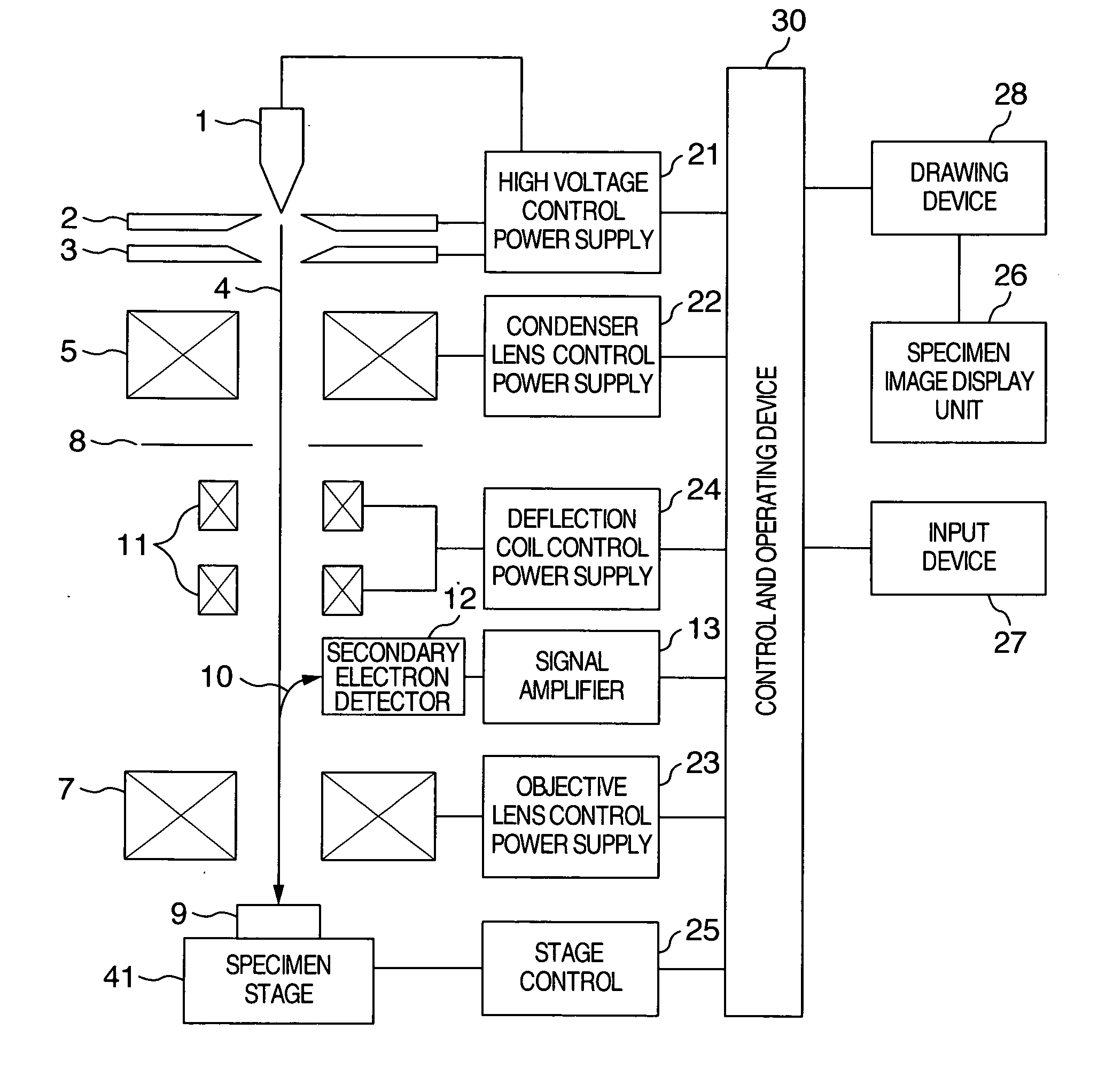
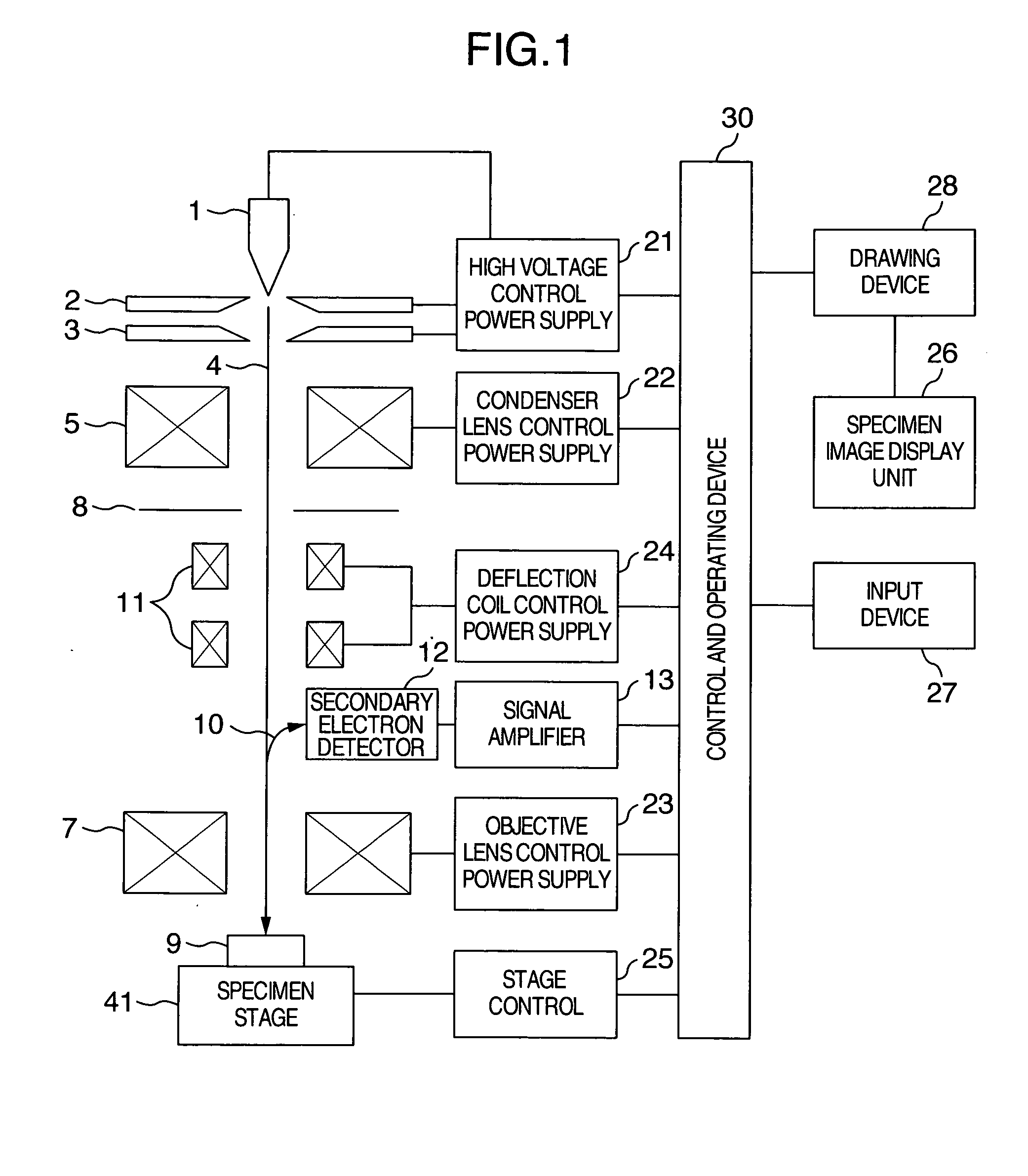
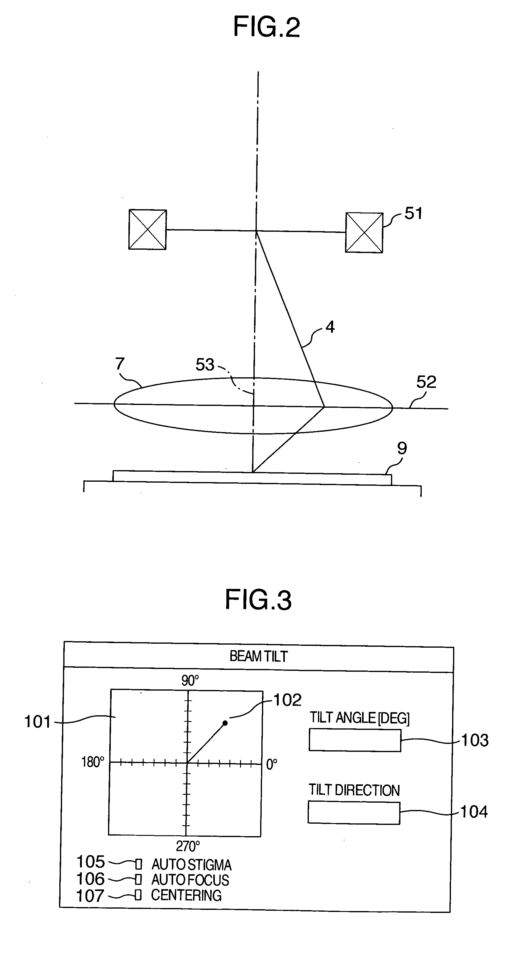
[0036] A GUI (graphical user interface) screen used to set conditions for irradiating an electron beam while giving it a tilt is illustrated in FIG. 3. The control and operating device 30 has a program for displaying such a picture on the specimen image display unit 26. On the basis of information set on the GUI screen, the aforementioned control and operating device 30 calculates current or voltage supplied to the deflector 51.

[0037] A viewing point adjustment picture 101 is for setting irradiation direction and irradiation angle of the electron beam. By adjusting a viewing point position 102 on the viewing point adjustment picture 101, an irradiation direction of the electron beam and an irradiation angle thereof can be set. A tilt angle and a tilt direction are displayed at a tilt angle value indicator 103 and a tilt direction indicator 104, respectively, on the basis of the viewing point setting on the viewing point adjustment picture 101. Alternatively, the tilt angle and tilt...

embodiment 2

[0049] The automatic astigmatism correction (automatic stigmatization) explained in embodiment 1 will be detailed using a flowchart shown in FIG. 5. The stigmator is comprised of, for example, a multi-pole coil as shown in FIG. 6 and is interposed between cathode 1 and objective lens 7. The stigmator to be explained with reference to FIG. 6 is a two-dimensional sigmator in which astigmatic aberration correcting intensities in respective directions can be adjusted by adjusting signals stx and sty applied to the respective coils so as to correct an astigmatic aberration. In the present embodiment, astigmatism correction will be described by way of example of the two-dimensional astigmatism correction but this is not limitative and for example, a stigmator for making three-dimensional astigmatic aberration correction can also be applicable to the present embodiment.

[0050] Firstly, a magnification during astigmatism correction is acquired (S0012). If the magnification value is higher t...

embodiment 3

[0058] The automatic focus correction explained in connection with embodiment 1 will be detailed with reference to a flowchart of FIG. 8. When the lens intensity of objective lens is changed while placing the beam in tilt condition, the field of view moves. This is because the beam tilt causes an x-y direction component (when the objective lens optical axis direction is defined as z direction) to be included in the direction in which focus is to be adjusted. Described in the present embodiment is a focus adjustment method and the construction therefor which can conduct proper focus adjustment even when the view field movement occurs.

[0059] Firstly, at a beam not placed in tilt condition (top-down image) the center of FOV is set to a suitable pattern, in the FOV, then focus is adjusted using the pattern. Next, a desired beam tilt angle is set in a desired beam tilt direction (S0020). The beam tilt direction and beam tilt angle correspond to those set on the GUI screen of FIG. 3. In ...


PUM


Abstract

In an apparatus for obtaining an image by irradiating a charged particle beam on a specimen, a condition of the beam conditioned differently from vertical incidence as in the case of the beam being tilted is required to be adjusted. To this end, the apparatus has a controller for automatically controlling a stigmator, an objective lens and a deflector such that astigmatism is corrected, focus is adjusted and view filed shift is corrected. The controller has a selector for inhibiting at least one of the astigmatism correction, focus adjustment and FOV shift correction from being executed.

Description

BACKGROUND OF THE INVENTION [0001] The present invention relates to a method of adjusting a beam condition for a charged particle beam and a charged particle beam apparatus and more particularly, to a method of making astigmatism correction, focus correction and FOV (field of view) shift correction when giving the beam a tilt. [0002] In the charged particle beam apparatus represented by a scanning electron microscope, a charged particle beam is focused to a fine beam which in turn is scanned on a specimen to obtain desired information from the specimen (for example, a specimen image). In the charged particle beam apparatus as above, the resolving power becomes higher year by year and besides, recently, there is a growing need for obtaining a tilt image of a specimen by tilting a charged particle beam in relation to the specimen. This is accounted for by the fact that for acquisition of tilt images of the specimen, it is general to tilt a specimen stage but for the purpose of prevent...

Claims


Application Information

Patent Timeline
IPC IPC(8): G21K5/04G21K1/08G21K7/00H01J37/153
CPCH01J37/153H01J2237/221H01J2237/216H01J37/21
Inventor MOROKUMA, HIDETOSHIARAI, NORIAKIDOI, TAKASHISASAJIMA, FUMIHIROKIMURA, YOSHIHIRO
Owner HITACHI HIGH-TECH CORP
Why Eureka
Try Eureka