MRI imageable medical device

Inactive Publication Date: 2005-10-27
BIOPHAN TECH
View PDF99 Cites 43 Cited by
  • Summary
  • Abstract
  • Description
  • Claims
  • Application Information

AI Technical Summary

Benefits of technology

[0017] In accordance with this invention, there is provided a medical device comprised of a lumen that inhibits distortion of medical resonance images taken of the device. When the device is exposed to radio frequency electromagnetic radiation with a frequency of from 10 megahertz to about 200 meg

Problems solved by technology

However, various stent designs substantially distort the surrounding of the stent during a Magnetic Resonance Imaging procedure” (see paragraph 0002).
Although coronary magnetic resonance angiography (MRA) has been successfully implemented for visualization of the native proximal and middle portions of the coronary artery tree, the in-stent lumen cannot now be visualized because of susceptibility artifacts and radiofrequency shielding, resulting in a local signal void.”
Furthermore, the stent Faraday Cage likely impedes the escape of whatever signal is generated in the lumen.
The stent's high magnetic susceptibility, however, perturbs the magnetic field in the vicinity of the implant.
This alters the resonance condition of protons in the vicinity, thus leading to intravoxel dephasing with an attendant loss of signal.
The net result with current metallic stents, most of which are stainless steel, is a signal void in the MRI images.
It is this structure that creates a Faraday Cage, and its associated problems with MRI.
But a current considerable factor weighing against the use of magnetic resonance imaging techniques to visualize implanted stents composed of ferromagnetic or electrically conductive materials is the inhibiting effect of such materials.
These materials cause sufficient distortion of the magnetic resonance field to preclude imaging the interior of the stent.
However, the Melzer solution lacks a suitable integration of an LC circuit within the stent.” The Alt p

Method used


Image

  • MRI imageable medical device
  • MRI imageable medical device
  • MRI imageable medical device

Examples


Embodiment Construction

[0083] In the first part of this specification, certain assemblies that contain nanomagnetic material, and / or certain processes for making nanomagnetic material, will be briefly described. Thereafter, in the second part of this specification, an improved stent assembly whose lumen is readily imageable under magnetic resonance imaging conditions will be described.

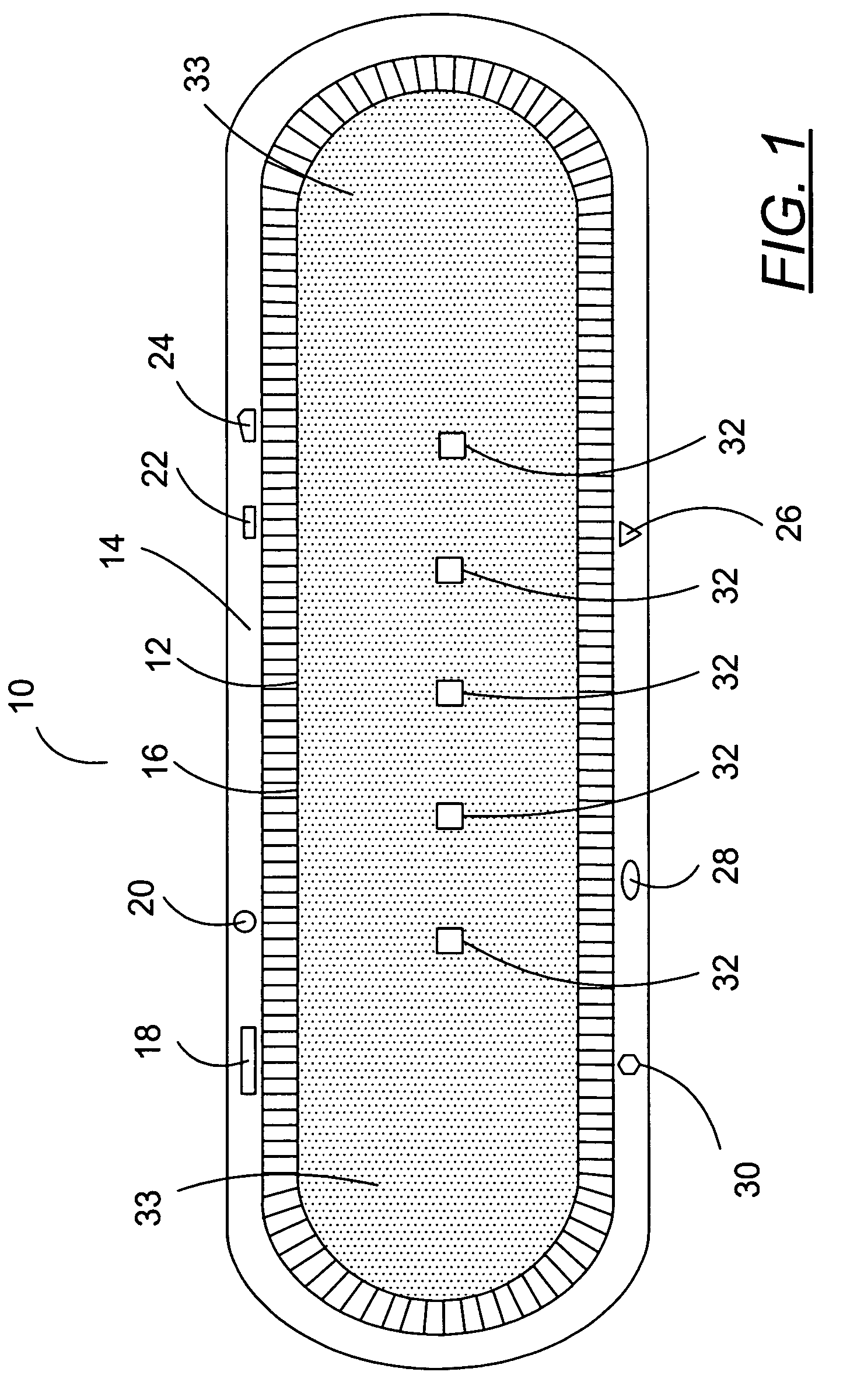
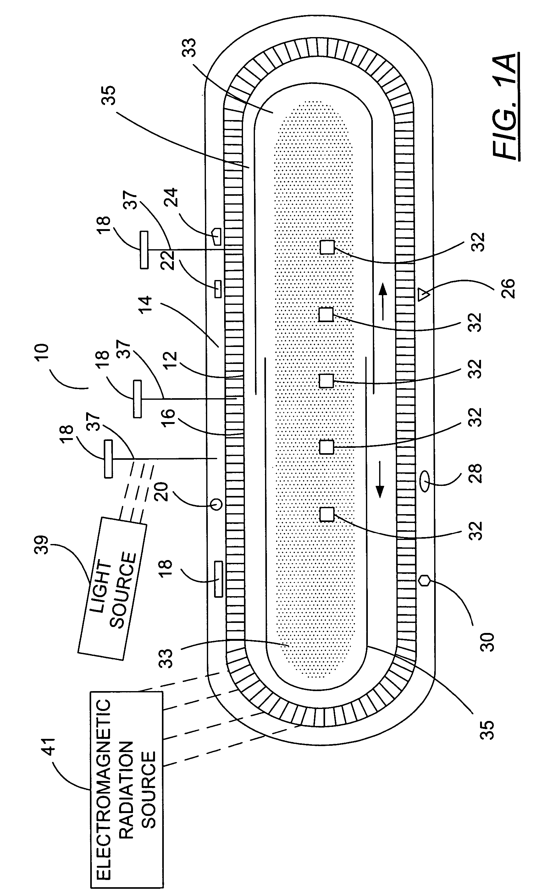
[0084]FIG. 1 is a schematic diagram of a preferred seed assembly 10 of this invention that may, in one preferred embodiment, contain nanomagnetic material. The FIGS. 1 and 1A of this specification are substantially identical to the FIGS. 1 and 1A of published United States patent application U.S. 2005 / 0025797, published on Feb. 5, 2005, the entire disclosure of which is hereby incorporated by reference into this specification; in particular, and without limitation, the disclosure of pages 2 through 40 of such published patent application, are hereby incorporated by reference into this specification.

[0085] Referring again t...


PUM

PropertyMeasurementUnit
Lengthaaaaaaaaaa
Fractionaaaaaaaaaa
Fractionaaaaaaaaaa

Abstract

A coated assembly with an inductance of from about 0.1 to about 5 nanohenries and a capacitance of from about 0.1 to about 10 nanofarads. The coated assembly contains a stent and a coating. When the assembly is exposed to radio frequency electromagnetic radiation with a frequency of from 10 megahertz to about 200 megahertz, at least 90 percent of the electromagnetic radiation penetrates to the interior of the stent.

Description

CROSS-REFERENCE TO RELATED PATENT APPLICATION [0001] This patent application is a continuation in part of each of applicants' copending patent application Ser. No. 10 / 887,521 (filed on Jul. 7, 2004), Ser. No. 10,867,517 (filed on Jun. 14, 2004), Ser. No. 10 / 810,916 (filed on Mar. 26, 2004), Ser. No. 10 / 808,618 (filed on Mar. 24, 2004), Ser. No. 10 / 786,198 (filed on Feb. 25, 2004), Ser. No. 10 / 780,045 (filed on Feb. 17, 2004), Ser. No. 10 / 747,472 (filed on Dec. 29, 2003), Ser. No. 10 / 744,543 (fled on Dec. 22, 2003), Ser. No. 10 / 442,420 (filed on May 21, 2003), and Ser. No. 10 / 409,505 (flied on Apr. 8, 2003). The entire disclosure of each of these patent applications is hereby incorporated by reference into this specification.FIELD OF THE INVENTION [0002] A medical device comprised of a lumen that inhibits distortion of medical resonance images taken of the device. When the device is exposed to radio frequency electromagnetic radiation with a frequency of from 10 megahertz to about 20...

Claims


Application Information

Patent Timeline
IPC IPC(8): A61L31/08A61L31/18A61N1/16A61N2/00A61N2/06H02J7/00
CPCA61L31/082A61L31/16A61L31/18A61N2/06A61N1/16A61N2/002A61L2300/00
Inventor WANG, XINGWUGREENWALD, HOWARD J.
Owner BIOPHAN TECH
Why Eureka
Try Eureka