Plasma display panel

a technology of display panel and plasma, which is applied in the direction of gas discharge electrode, sustain/scan electrode, gas discharge electrode, etc., can solve the problems of weak discharge and eventually disappearance, low efficiency (a ratio of luminance to power consumption) of conventional pdp, and low efficiency of pdp in terms of energy conversion, so as to improve the structure of the electrodes, enhance efficiency, and reduce the required voltage for discharge

Inactive Publication Date: 2005-11-03
SAMSUNG SDI CO LTD
View PDF9 Cites 8 Cited by
  • Summary
  • Abstract
  • Description
  • Claims
  • Application Information

AI Technical Summary

Benefits of technology

[0014] In accordance with the present invention, a PDP is provided in which the efficiency is enhanced as well as the required voltage for the discharge is lowered by improving the structure of the electrodes causing the address discharge and the sustain discharge.

Problems solved by technology

Therefore, the net voltage difference across the gas between the Y electrode and the address electrode becomes smaller than the initial address voltage Va, and causes the discharge to be weak and disappear eventually.
In order to obtain the visible light as aforementioned, the conventional PDP requires many steps which are not efficient in terms of energy conversion.
Therefore, a large consumption of electric power results, and consequently, the efficiency (a ratio of luminance to the power consumption) of the PDP is not as good as that of a cathode ray tube type of display device.
Also, as between the X electrode and the Y electrode, only a surface discharge occurs that is not efficient as compared to the face discharge.

Method used


Image

  • Plasma display panel
  • Plasma display panel
  • Plasma display panel

Examples


Embodiment Construction

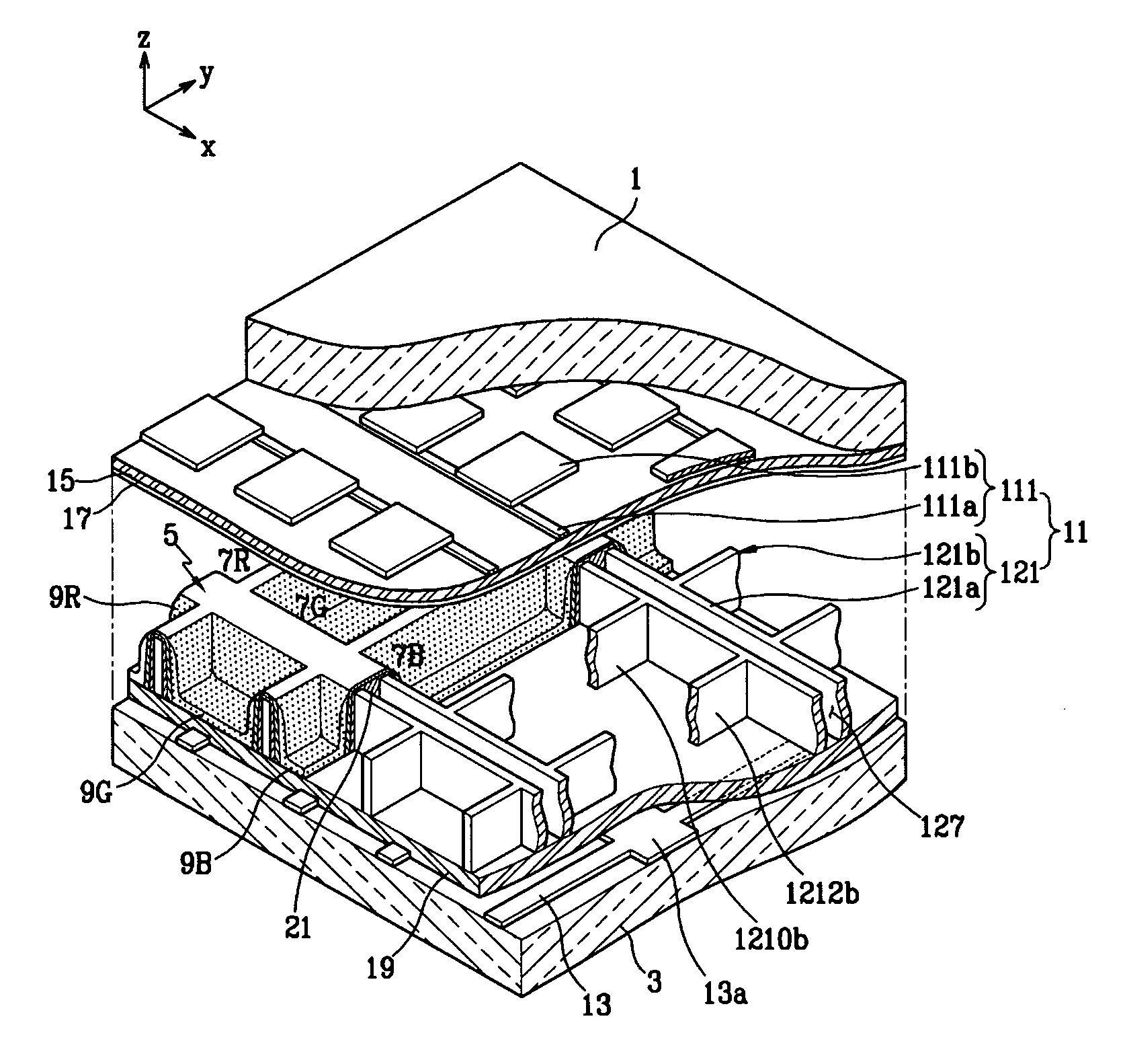
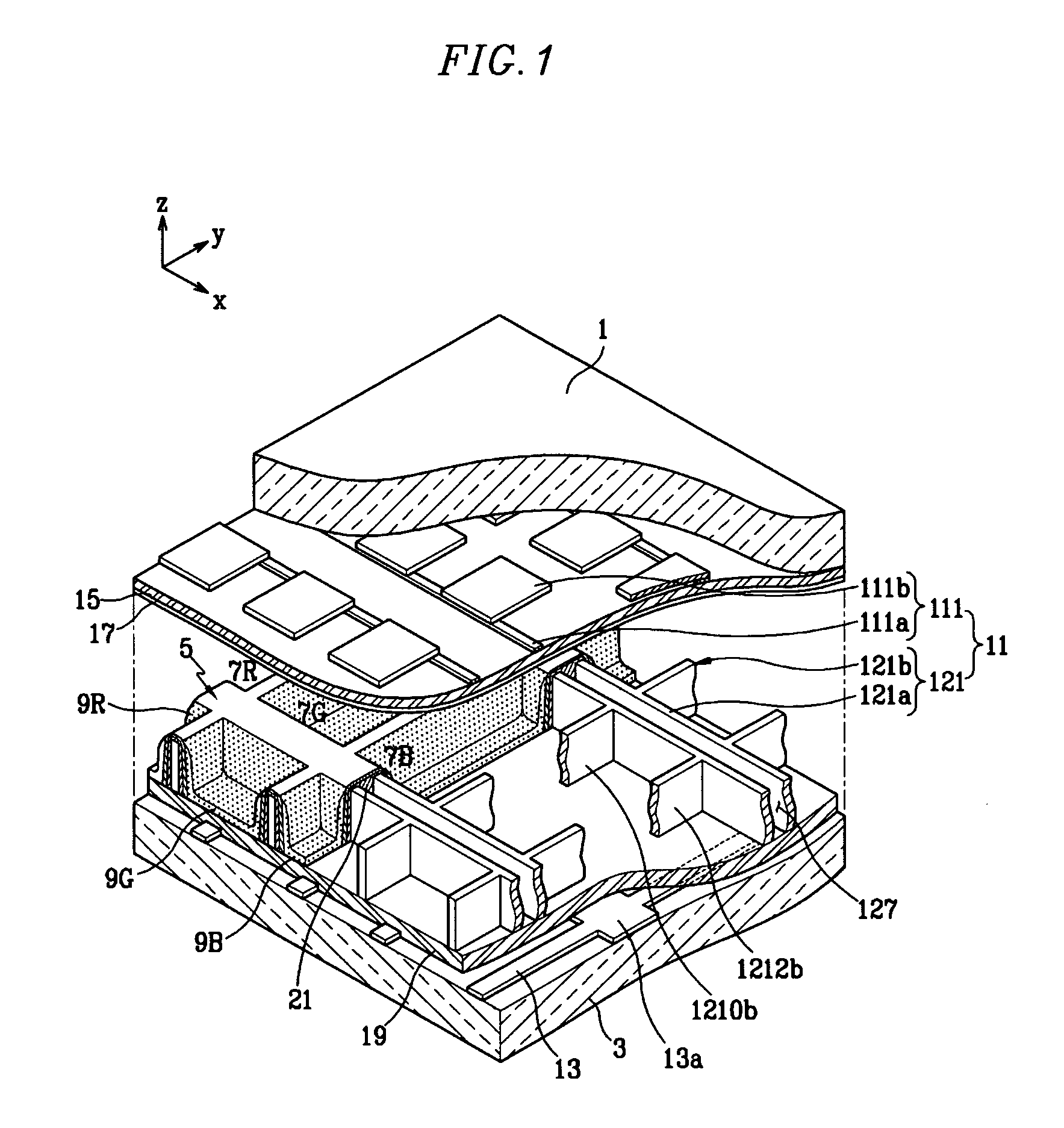
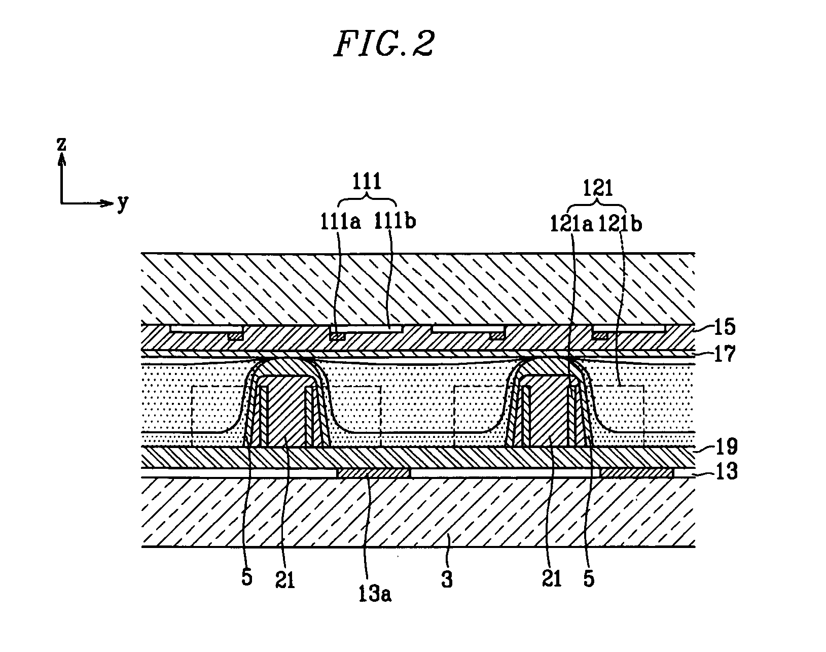
[0031] As shown in the drawings, a PDP in accordance with the present invention includes a first substrate 1 and a second substrate 3 facing the first substrate 1, both hermetically joined at their edges to form a vacuum tight vessel. Between the first substrate 1 and the second substrate 3, barrier ribs 5 form a plurality of discharge cells 7R, 7G, 7B by dividing the space therebetween. Since the discharge cells 7R, 7G, 7B are formed into polyhedral discharge spaces (for example, hexahedron), the discharge cell may be a closed space surrounded by the barrier ribs 5, the first substrate 1 and the second substrate 3. For example, the discharge cells 7R, 7G, 7B are formed in a lattice pattern.

[0032] Phosphor layers 9R, 9G, 9B are formed by painting R, G and B phosphors inside the discharge cells 7R, 7G, 7B.

[0033] In order to produce an image by visible light emitted from the gas discharge inside the PDP, the PDP includes principal electrodes, which are display electrodes and address...


PUM


Abstract

A plasma display panel is provided. A first substrate faces a second substrate. Barrier ribs positioned between the first substrate and the second substrate form a plurality of polyhedral discharge cells. A plurality of display electrodes formed substantially along a first direction of the first substrate have portions placed at positions corresponding to at least three planes of the discharge cell's composing planes. A dielectric layer for the display electrode covers the display electrodes. A plurality of address electrodes formed along a second direction of the second substrate have portions placed at positions corresponding to at least one plane of the discharge cell's composing planes. A dielectric layer for the address electrode covers the address electrodes. A phosphor layer is formed inside the discharge cells.

Description

CROSS-REFERENCE TO RELATED APPLICATION [0001] This application claims the benefit of and priority to Korean Patent Application No. 10-2004-0029885, filed on Apr. 29, 2004 in the Korean Intellectual Property Office, the entire disclosure of which is incorporated herein by reference. BACKGROUND OF THE INVENTION [0002] (a) Field of the Invention [0003] The present invention relates to a plasma display panel (PDP) and, in particular, to a display electrode of the PDP. [0004] (b) Description of the Related Art [0005] A typical PDP is a display device in which vacuum ultraviolet rays from plasma generated by gas discharge excite phosphors to emit red (R), green (G), blue (B) visible light for producing an image. Such a PDP can achieve a large screen size over 60 inches while keeping its thickness within 10 cm. The PDP has features of excellent color reproduction and no distortion along its viewing angle. As compared to a liquid crystal display (LCD) device, the PDP has the advantage of a ...

Claims


Application Information

Patent Timeline
Patent Type & Authority Applications(United States)
IPC IPC(8): H01J17/04H01J17/49
CPCH01J11/12H01J11/28H01J11/24H01J11/16H01J2211/323H01J2211/326
Inventor MIZUTA, TAKAHISA
Owner SAMSUNG SDI CO LTD
Why Eureka
Try Eureka