Temperature monitoring system

a technology of temperature monitoring system and temperature image, which is applied in the direction of thermometers, instruments, electrical/magnetic means, etc., can solve the problems of geometric distortion of the temperature image constructed according to the above method with respect to the plastic sheet, more serious distortion, and the speed is far from uniform, so as to eliminate the cost and time associated with the use of calibration sheets and improve resolution.

Active Publication Date: 2005-11-03
LAND INSTRUMENTS INTERNATIONAL
View PDF1 Cites 4 Cited by
  • Summary
  • Abstract
  • Description
  • Claims
  • Application Information

AI Technical Summary

Benefits of technology

[0055] This system requires no calibration object, instead performing a full co-ordinate transformation based on measurements of the machine / scanner geometry which results in an accurate, corrected image. The expense and time associated with the use of a calibration sheet is eliminated and the resolution is greatly improved. Moreover, user intervention is reduced to a minimum, since the system itself performs the required correction. Further, this technique compensates the raw data rather than the image “result”. Here, the compensated data can be used to build up the desired image from a complete set of raw data. Prior art techniques, such as that described above, merely produce a compensated result by organising a subset of the raw data into a geometrical arrangement to appear as though it is a corrected image of the raw data.

Problems solved by technology

However, a temperature image constructed according to the above method is geometrically distorted with respect to the plastic sheet.
This leads to a more serious distortion.
Further, the speed is far from uniform.
As a result, temperature images obtained using linescanners suffer massive geometrical distortion.
It is very difficult to visually relate the resulting temperature images to the sheet or to the zone pattern of the heater panel.
The use of a calibration object is expensive and time consuming, requiring a new calibration sheet for each new heating pattern or sheet size and shape.
As a result, calibration is not performed in real time.
Each of these steps will introduce error.
Further, the accuracy of the calibrated image is inherently low since the resolution is limited to zones and the system cannot compensate for unexpected variations in sheet position, velocity or acceleration.

Method used


Image

  • Temperature monitoring system
  • Temperature monitoring system
  • Temperature monitoring system

Examples


Embodiment Construction

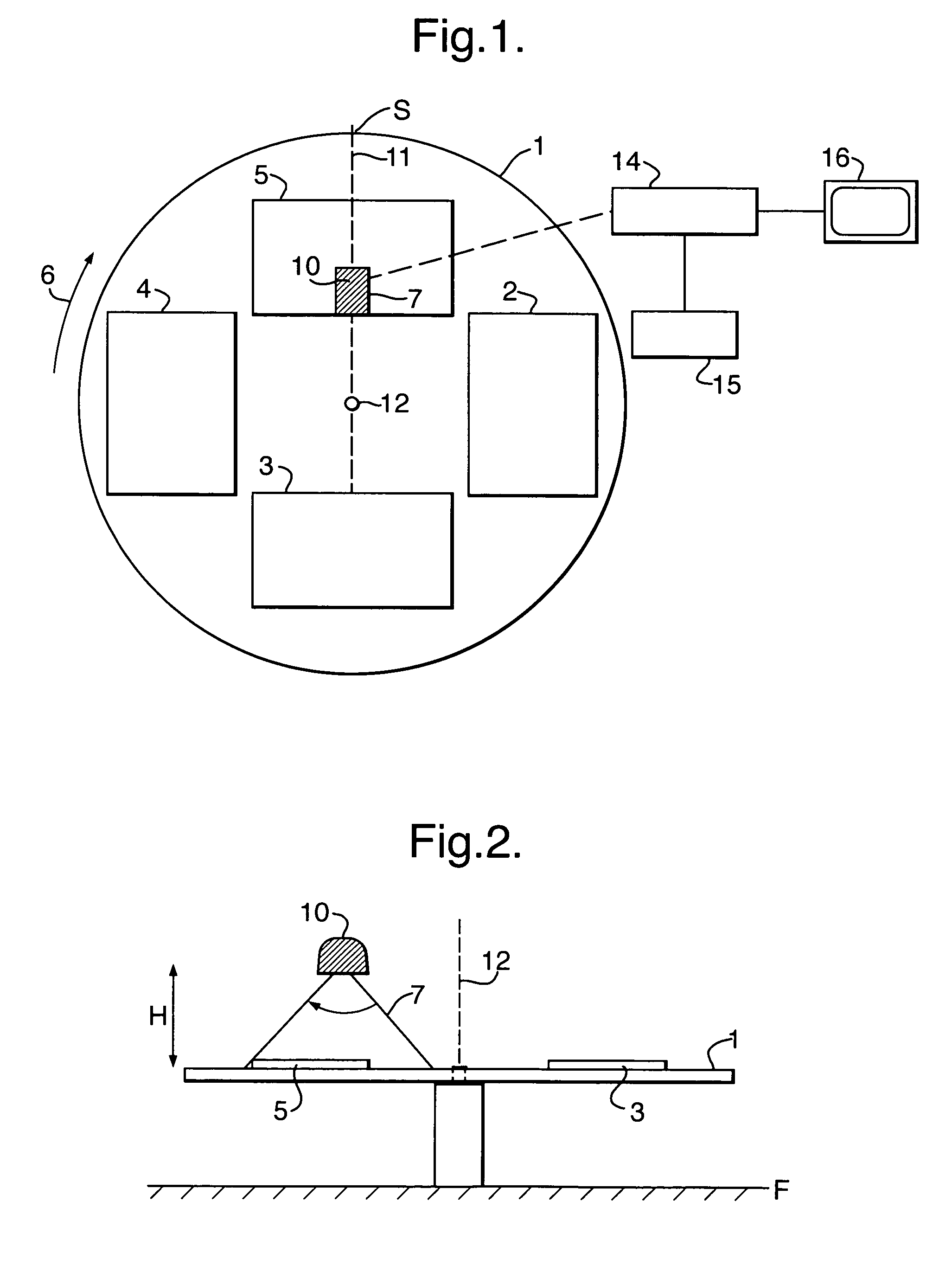
[0068] The rotary thermoforming machine shown in the drawings comprises a carousel 1 on which are provided four plastic sheets 2 to 5. In operation, the carousel 1 is rotated in the direction of an arrow 6 so as to bring each sheet 2 to 5 to respective load, heat, form and cool stations.

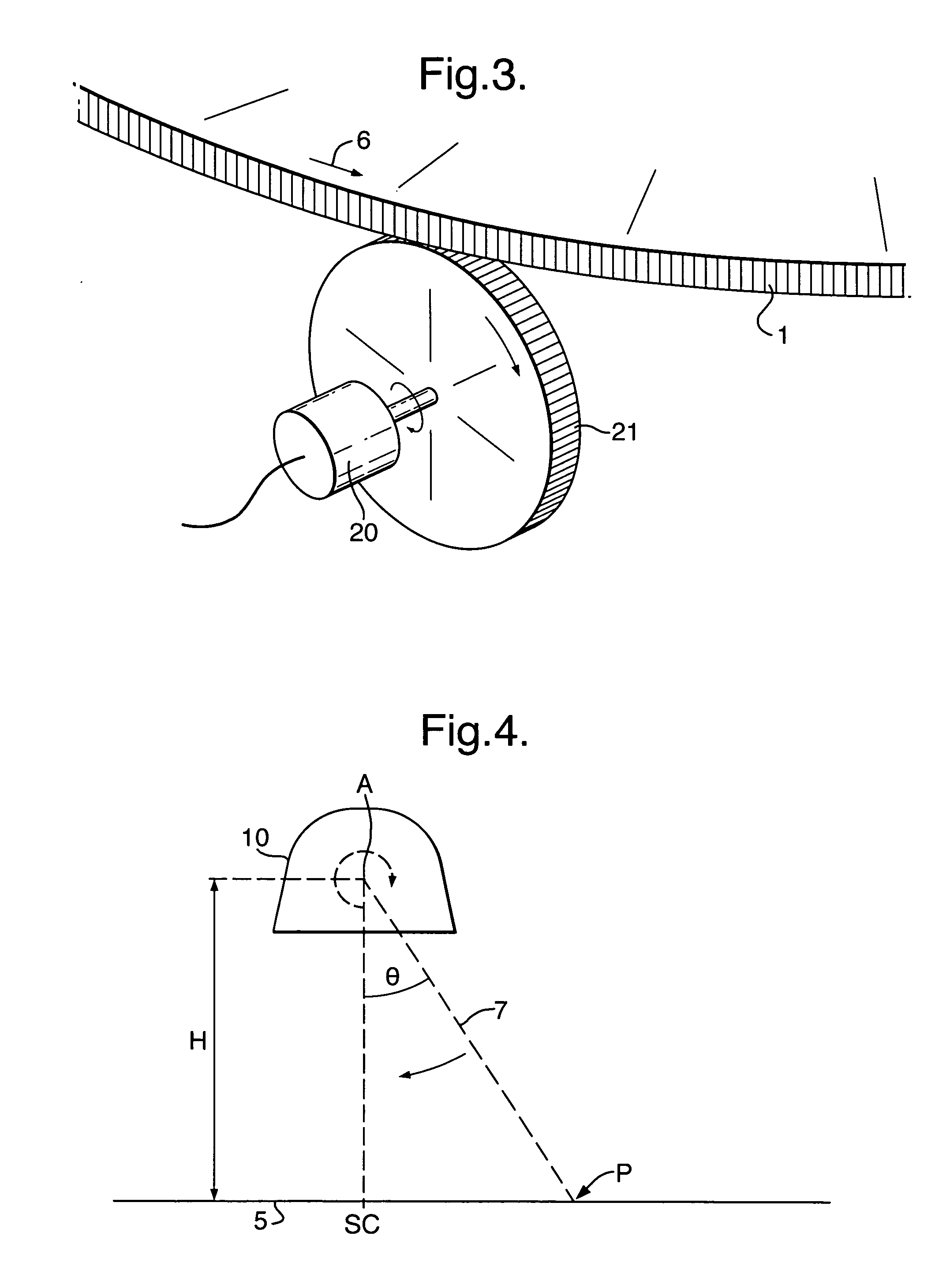
[0069] Located above the carousel 1 is a linescanner 10 shown in more detail in FIGS. 2 and 4. The linescanner 10 comprises a photodetector or the like together with a pivoted mirror (not shown) and an in-built laser. The laser generates a beam of light 7 which is rapidly scanned by the mirror along a scan line 11 in a scan plane S, extending radially from the axis 12 of rotation of the carousel 1.

[0070] The linescanner 10 is connected to a microprocessor 14 which in turn is connected to a data store 15 and a monitor display 16.

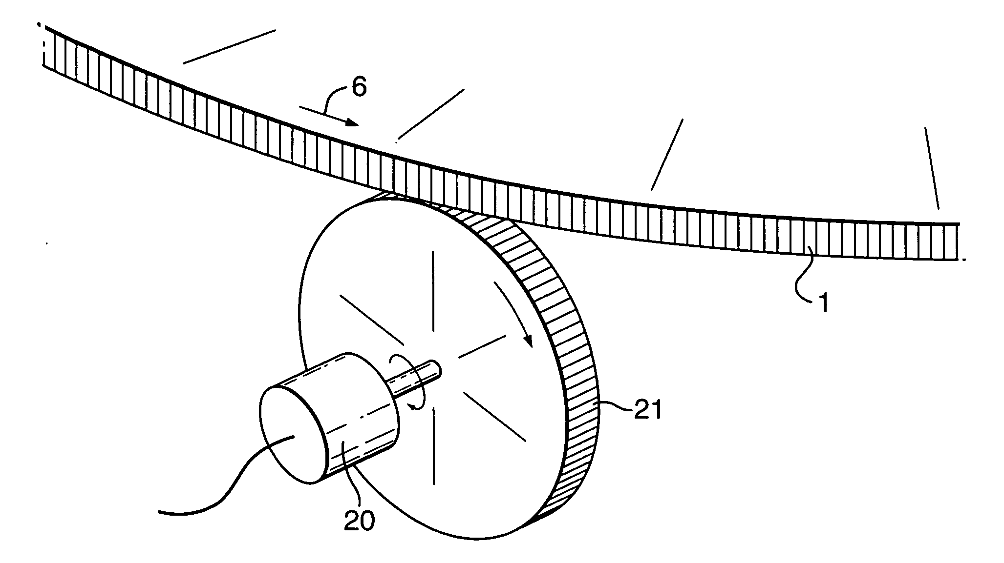
[0071] The carousel 1 is continuously rotated by a motor (not shown) and the rotational position is determined by a rotary encoder 20 coupled with a rubber friction wheel 2...


PUM

PropertyMeasurementUnit
half-angleaaaaaaaaaa
wavelength bandaaaaaaaaaa
temperature monitoringaaaaaaaaaa

Abstract

A temperature monitoring system for generating a representation of the temperature of the regions of a heated sheet of a rotary thermoforming machine comprises a temperature detector for detecting the respective temperatures of areas of the sheet extending in a line across the sheet, a system for monitoring relative movement between the sheet and the temperature detector; and a processing system for a) recording the coordinates and temperature of each area whose temperature is monitored; and b) determining the temperature of regions of the sheet defined on a different basis to the areas by applying a predetermined algorithm to the data stored in step a) which takes account of the rotary movement of the sheet.

Description

CROSS-REFERENCES TO RELATED APPLICATIONS [0001] This application claims priority from GB Application No. 0406653.6, filed Mar. 24, 2004, the entire disclosure of which is incorporated by reference. BACKGROUND OF THE INVENTION [0002] The invention relates to a temperature monitoring system for use with a rotary thermoforming machine. In a particular example it relates to use of an infra-red linescanner to obtain temperature images of plastic sheets on the “carousel” of a rotary thermal forming machine. [0003] In typical thermal forming processes, plastic sheets are heated prior to being formed into various articles. Examples of such articles include baths, refrigerator liners, car dashboards and yoghurt cartons. [0004] Heating softens the plastics material, and is usually carried out by placing the plastic sheet underneath a heater panel or between two such panels. Forming is then usually carried out by “sucking” the softened sheet into a mould. Typically this is achieved by creating...

Claims


Application Information

Patent Timeline
Patent Type & Authority Applications(United States)
IPC IPC(8): B29C51/22B29C51/42B29C51/46G01J5/00
CPCB29C51/22B29C51/46B29C51/422
Inventor ORTMANN, JORG
Owner LAND INSTRUMENTS INTERNATIONAL
Why Eureka
Try Eureka