

Fuel cell system
a fuel cell and system technology, applied in the direction of fuel cells, solid electrolyte fuel cells, fuel cells, etc., can solve the problems of affecting the maintenance of stable system power generation, the drop in power generation efficiency etc., and achieve the effect of improving the performance of the fuel cell system
- Summary
- Abstract
- Description
- Claims
- Application Information
AI Technical Summary
Benefits of technology
Problems solved by technology
Method used
Image

Examples
first embodiment
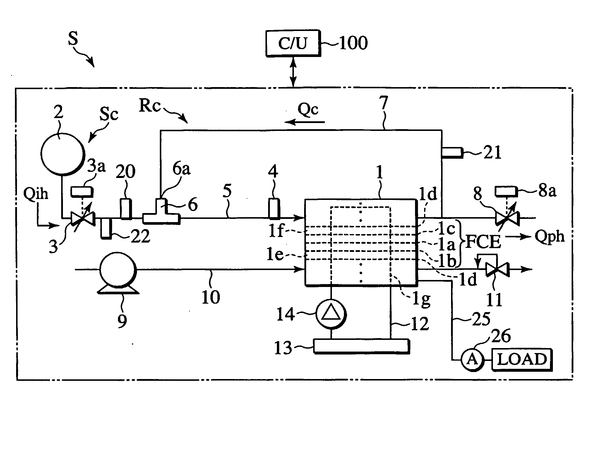
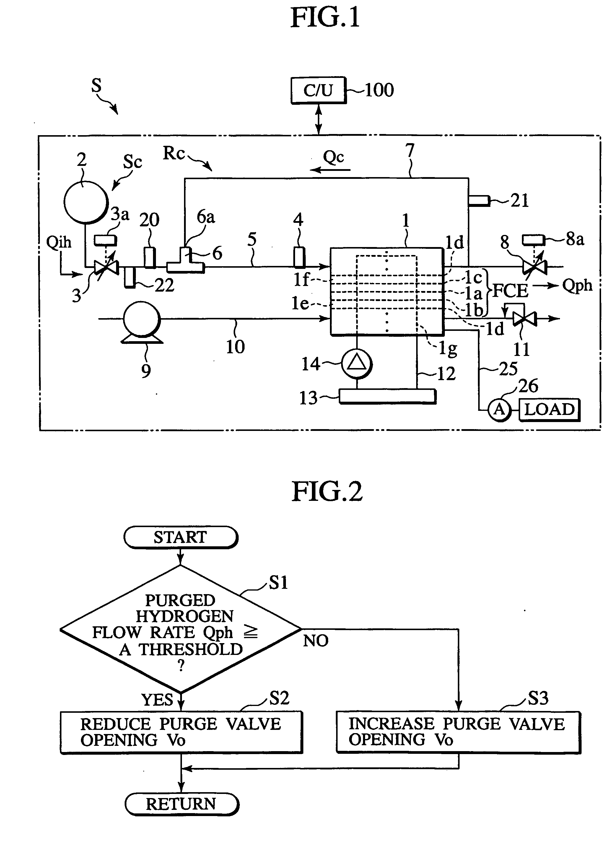
[0019] A fuel cell system S of a first embodiment illustrated in FIG. 1, includes a fuel cell stack 1 which generates electrical power from hydrogen fuel gas, a fuel tank 2 for storing the fuel gas, an ejector 6 which pumps the fuel gas for recirculating in the system, and a purge valve 8 which purges nitrogen contained in the fuel gas by discharging the fuel gas to the atmosphere together with the nitrogen.
[0020] In the fuel cell stack 1, cathode (as oxidant electrode, or air electrode) 1b and anode (as fuel electrode) 1c are provided so as to be parallel to each other with a polymer electrolyte membrane 1a interposed therebetween. These elements arranged in this manner collectively constitute a fuel cell element FCE. Each fuel cell element FCE is further sandwiched by a pair of separators 1d. The fuel cell stack 1 is constituted of a plurality of these sandwiched FCE stacked on each other. The fuel gas is introduced into anode flow channels 1f provided between the anode 1c and the...
second embodiment
[0055] The supplied hydrogen flow rate Qih is calculated only from the regulator inlet pressure Ph3 when the valve opening degree Vr of the regulator 3 is small enough for the regulator 3 to be in a choked state. When the regulator inlet pressure Ph3 is in an unchoked state, the supplied hydrogen flow rate Qih is calculated from the regulator inlet pressure Ph3 and the regulator outlet pressure Ph2. In the second embodiment, a temperature sensor 24 provided in the coolant passage 12 of the fuel cell stack 1 to detect a coolant temperature Tw. Since the fuel gas and the coolant exchange heat in the fuel cell stack 1, the coolant temperature Tw and the fuel gas temperature Th2 are approximately equal to each other, and it is possible to use the coolant temperature Tw as the fuel gas temperature estimate the fuel gas temperature from. Moreover, the coolant is in the form of liquid, which provides better responsiveness for temperature measurement than gas. Even if the coolant temperatur...
third embodiment
[0058] Next, the present invention will be described.
[0059] The third embodiment is different from the first or second embodiment in that an improvement is made for the calculation of Qe which is the rate of hydrogen consumption by the electrical power generation of the fuel cell stack 1. As described above, Qeh that is the flow rate of hydrogen to be consumed without being purged is calculated based on Qe. Other elements are the same as those of the first or second embodiment.
[0060] A fuel cell system S for a vehicle is required to cope with the rapidly changing load on the system S and to be capable of adjusting the output of the fuel cell stack 1 depending on the changing load. For variable output thereof, the pressure Ph2 of the fuel gas supplied to the fuel cell stack 1 is controlled. In order to increase the supply pressure of the fuel gas, it is necessary to supply hydrogen to the fuel recirculation system Rc at a rate more than Qeh that is calculated from the rate of hydrog...
PUM
| Property | Measurement | Unit |
|---|---|---|
| concentration | aaaaa | aaaaa |
| flow rate | aaaaa | aaaaa |
| threshold | aaaaa | aaaaa |
Abstract
Description
Claims
Application Information