

Method for detecting position errors using a motion detector
a motion detector and position error technology, applied in the field of industrial robot monitoring, can solve the problems of inability to calibrate robots in factory environments, the published positioning accuracy specifications often do not meet industry needs, and the system generally cannot be used for calibrating robots, etc., to prevent product faults, machine damage, waste of resources, etc., to achieve accurate prediction of robot position errors, the effect of low cos
- Summary
- Abstract
- Description
- Claims
- Application Information
AI Technical Summary
Benefits of technology
Problems solved by technology
Method used
Image

Examples
experiment 1
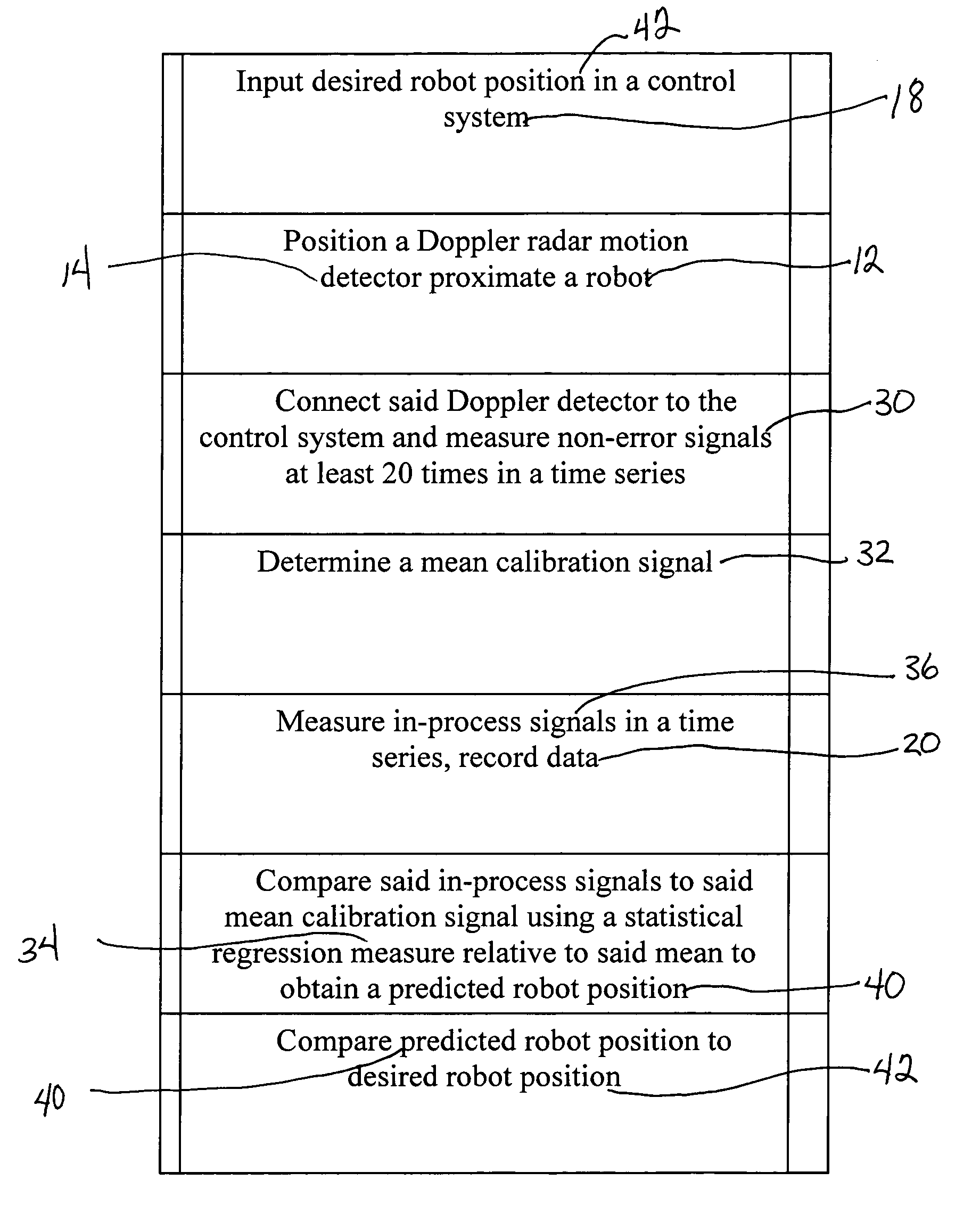
[0066] The objectives of Experiment 1 were to: [0067] 1. Experimentally verify the repeatability of the Seiko D-TRAN RT-2000 robot used for testing, [0068] 2. Experimentally verify that a dial gauge could be used to precisely measure robot position, and [0069] 3. Experimentally determine if there is significant drift in the robot during cycling.
[0070] The method used to experimentally determine robot repeatability and drift characteristics consisted of five steps: [0071] 1. Command the robot to move to a test position 20 times, [0072] 2. Measure the position of the robot using a dial gauge, [0073] 3. Cycle the robot, between the workspace origin and the test position, for 3 hours, [0074] 4. Command the robot to move to the test position 20 times.
[0075] 5. Measure the position of the robot using a dial gauge.
TABLE 2Robot position dial gauge measurements for Experiment 1StepBefore Cycling (inches)After Cycling (inches)00.501—10.5030.50120.5030.50230.5020.50140.5030.50150.5030.5016...
experiment 2
[0082] The objective of Experiment 2 was to: [0083] 1. Experimentally verify that the dial gauge could accurately detect single-axis robot position errors, for the given robot.
[0084] The method used to experimentally verify that the dial gauge could accurately detect single-axis position errors consisted of two steps: [0085] 1. Command the robot to move to the test position±0.03 T-axis degrees, in 0.003 degree increments (the robot's T-axis accuracy specification is 0.003 degrees, which corresponds to 0.001 inches at the given test position). [0086] 2. Measure the position of the robot using the dial gauge.
[0087] Table 3 shows the 21 positions about the test point to which the Seiko D-TRAN RT-2000 robot was commanded to move (values in millimeters), as well as the corresponding dial gauge measurements (in inches).
TABLE 3Robot position dial gauge measurements for Experiment 2PositionXYDial GaugeStep(degrees)(mm)(mm)(inches)1−89.9700.313−597.0560.4882−89.9730.281−597.0560.4903−89....
experiment 3
[0094] The objectives of Experiment 3 were to: [0095] 1. Develop a measure from sensor signal samples for determining robot position, [0096] 2. Determine how well the sensor signal measure represents robot position, and [0097] 3. Establish a mean signal to represent the robot moving to the correct test position.
[0098] The method used to experimentally achieve Experiment 3 objectives consisted of six steps: [0099] 1. Cycle the robot 20 times between home position and the nominal test position. [0100] 2. Measure robot position with the dial gauge. [0101] 3. Measure the sensor signal as the robot moves between home and the nominal test position. Sample the sensor signal at 0.1 msec intervals. [0102] 4. Average the values of the 20 sensor signals at each sampling time step to find the mean calibration sensor signal value at each sampling time step. (See FIG. 6) [0103] 5. Compute a root sum of squares error measure for each of the 20 sensor signals by summing squared error for each time...
PUM
 Abstract
Description
Claims
Application Information