Tin plating method

a technology applied in the field of tin and tinalloy plating, can solve the problems of achieve the effect of greatly reducing increasing the tendency to whisker formation

Active Publication Date: 2005-11-10
ROHM & HAAS ELECTRONICS MATERIALS LLC
View PDF9 Cites 27 Cited by
  • Summary
  • Abstract
  • Description
  • Claims
  • Application Information

AI Technical Summary

Benefits of technology

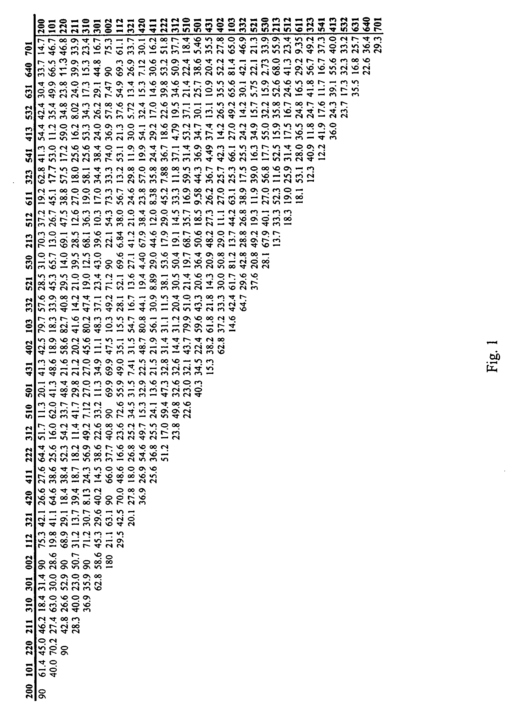
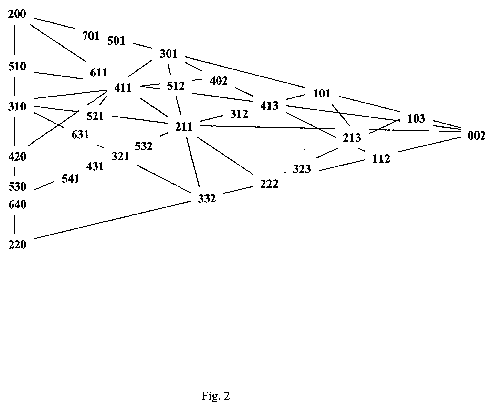
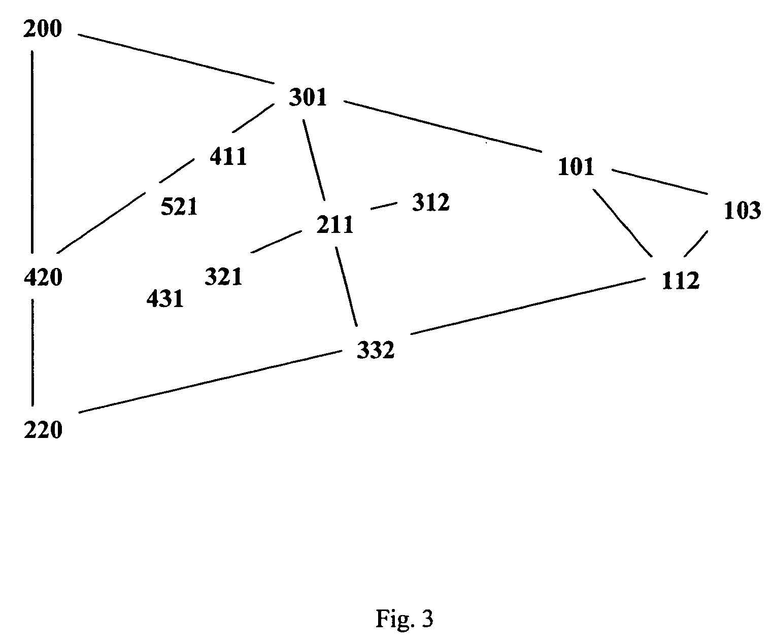
[0010] It has been surprisingly found that tin whisker formation can be greatly reduced by providing a tin or tin-alloy film or layer in which the tin or tin-alloy layer is substantially free of crystal planes or equivalent planes thereof forming an angle of 5° to 22° with an adjacent crystal plane or an equivalent plane thereof. Such a condition increases the tendency to whisker formation.

Problems solved by technology

Such a condition increases the tendency to whisker formation.

Method used


Image

  • Tin plating method
  • Tin plating method
  • Tin plating method

Examples


example 1

[0053] A plating bath is prepared by combining 50 g / L tin as tin(II) methane sulfonate, 160 g / L free methane sulfonic acid, 25 g / L ethoxylated beta-naphthol containing 8 moles EO, and 5 g / L ethoxylated bisphenol A. A copper substrate is electroplated in the bath at a temperature of 40° C. and a current density of 20 A / dm2 using direct current plating. X-ray diffraction analysis is conducted on the plated sample for a 2Θ-angle of 20° to 100° using a Phillips X-ray diffraction instrument.

example 2

[0054] The procedure described in Example 1 is repeated, except using a plating bath prepared by combining 40 g / L tin as tin(II) methane sulfonate, 200 g / L free methane sulfonic acid, 25 g / L ethoxylated beta-naphthol containing 8 moles EO, and 5 g / L ethoxylated bisphenol A.

example 3

[0055] The procedure described in Example 1 is repeated, except using a plating bath prepared by combining 60 g / L tin as tin(II) methane sulfonate, 240 g / L free methane sulfonic acid, 25 g / L ethoxylated beta-naphthol containing 13 moles EO, and 5 g / L ethoxylated bisphenol A.


PUM

PropertyMeasurementUnit
angleaaaaaaaaaa
diameteraaaaaaaaaa
thicknessaaaaaaaaaa

Abstract

Tin deposits having greatly reduced whisker formation are provided. Methods of depositing tin layers or films having a reduced tendency to form whiskers are also provided.

Description

CROSS-REFERENCE TO RELATED APPLICATIONS [0001] This application claims the benefit under 35 U.S.C. § 119(e) of U.S. Provisional Application Nos. 60 / 361,662, filed Mar. 5, 2002 and 60 / 408,788, filed Sep. 6, 2002, the entire contents of which applications are incorporated herein by reference.BACKGROUND OF THE INVENTION [0002] In general, the present invention relates to the field of tin and tin-alloy plating. In particular, the present invention relates to the reduction of whisker formation in a tin or tin-alloy film. [0003] Tin layers are typically used in the electronics industry to provide good solderability of components. For example, tin layers may be deposited on a copper lead frame to provide a solderable finish. Unfortunately, tin layers, particularly electrodeposited tin layers, are subject to spontaneous whisker formation. “Whiskers” are hair-like single crystals that grow from the surface of the tin layer. Tin whiskers may range in diameter from a few nanometers to several ...

Claims


Application Information

Patent Timeline
Patent Type & Authority Applications(United States)
IPC IPC(8): C25D3/30C25D7/12C25D3/32C25D7/00H05K3/24
CPCC25D3/30C25D3/32C25D7/00Y10T428/12715C25D7/12Y10T428/12722Y10T428/12708H05K3/244
Inventor EGLI, ANDRE
Owner ROHM & HAAS ELECTRONICS MATERIALS LLC
Why Eureka
Try Eureka