Integrated apparatus for removing pollutants from a fluid stream in a lean-burn environment with heat recovery

a technology of fluid stream and integrated apparatus, which is applied in mechanical apparatus, machines/engines, separation processes, etc., can solve the problems of pm/nox trade-off, complex diesel emissions, and remained problematic in the diesel engine industry, and achieve excellent noise absorption qualities and compact size.

Inactive Publication Date: 2005-11-17
PAGE DORRIAH L +2
View PDF4 Cites 26 Cited by
  • Summary
  • Abstract
  • Description
  • Claims
  • Application Information

AI Technical Summary

Benefits of technology

[0012] The present invention resides in an integrated apparatus for effectively and conveniently oxidizing and reducing pollutants in a variety of lean-burn environments. These environments include various types of engines, such as diesel internal combustion, dual-fuel (diesel and natural gas), dedicated spark-ignited lean-burn, and homogenous charge compression ignition. The apparatus preferably is positioned downstream of the turbocharger in the exhaust duct of a lean-burn engine.
[0013] The apparatus allows for treatment for particulate matter (PM), hydrocarbon (HC), carbon monoxide (CO) and nitrogen oxides (NOx) in one integrated system, and allows for recovery of heat from these reactions for preheat of the incoming exhaust stream to raise the internal catalyst temperature.
[0015] The DPF provides catalytic treatment of HC, CO and PM. The DPF captures PM from the stream, and is regenerated to prevent pressure drop from collected PM on the filter becoming excessive. The DPF is preferably a wall flow particulate filter made of a ceramic material such as cordierite, silicon carbide, mullite, or a number of other high temperature porous ceramic substrates. Alternative configurations to the wall-flow filter geometry include small pore ceramic foams, sintered metal meshes, and ceramic fiber yarns. All provide large filtration areas with pore sizes small enough to provide a filtering function.
[0020] The apparatus also can employ a fuel injector to inject HC into the stream at the inlet passage. This injected HC, when reacted over the LNC, DOC, or catalyzed DPF, can elevate the temperature at the DPF to improve the oxidation rate of the PM for regeneration. The apparatus also employs pressure, temperature and engine speed sensors, and also a controller to regulate the rate of HC injection to appropriate levels.
[0022] The apparatus enables a modern engine to achieve the increasingly difficult standards for heavy-duty engines, without significant changes in fuel injection equipment, and without employing advanced exhaust gas recirculation. The compact size and excellent noise abatement qualities of the apparatus also allow it to replace the existing muffler or silencer for an engine.

Problems solved by technology

Diesel emissions are more complex than those from gasoline engines, and their catalytic treatment is more complicated.
This characteristic, known as the PM / NOx trade-off, has remained problematic to the diesel engine industry.
Therefore, these engines continue to require exhaust aftertreatment to meet these tougher emissions standards.
Current catalyst technology can reduce the soluble organic fraction of the PM as well as CO and HC, but cannot reduce NOx.
Traditional automotive three-way catalysts cannot reduce NOx in excess air, such as is present in a lean-burn environment.
For NOx reduction, a catalyst that could decompose NOx to N2 and O2 would provide the ideal solution; however, such a catalyst has proven difficult to develop.
While oxidation catalysts are effective in oxidizing the SOF component of the PM, they are not effective in oxidizing solid carbon.
However, DPFs have not been in widespread use, principally because the collected PM builds up on the filter, eventually leading to high back-pressure, which leads to reduced power and fuel economy.
Further, excessive back-pressure from a blocked filter can damage the engine.

Method used


Image

  • Integrated apparatus for removing pollutants from a fluid stream in a lean-burn environment with heat recovery
  • Integrated apparatus for removing pollutants from a fluid stream in a lean-burn environment with heat recovery
  • Integrated apparatus for removing pollutants from a fluid stream in a lean-burn environment with heat recovery

Examples


Embodiment Construction

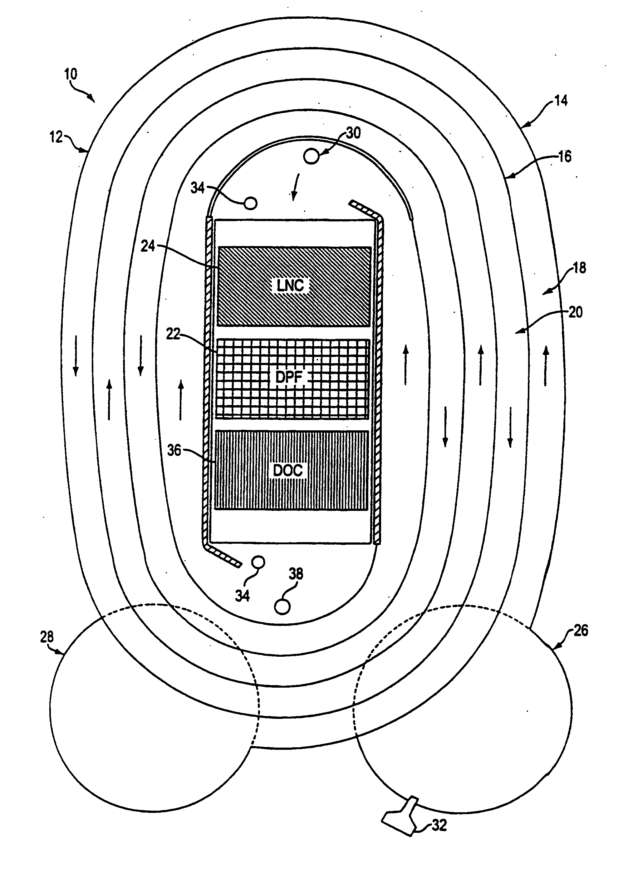
[0028] With reference now to the illustrative drawings, and particularly to FIG. 1, there is shown an apparatus 10 for treating fluid streams, such as emissions from lean-burn engines, for hydrocarbon (HC), particulate matter (PM), carbon monoxide (CO) and nitrogen oxides (NOx) in an integrated system. The apparatus can be positioned downstream of a turbocharger in the exhaust duct of an engine or other emissions source.

[0029] The outer surface of the apparatus forms a heat exchanger shell 12.

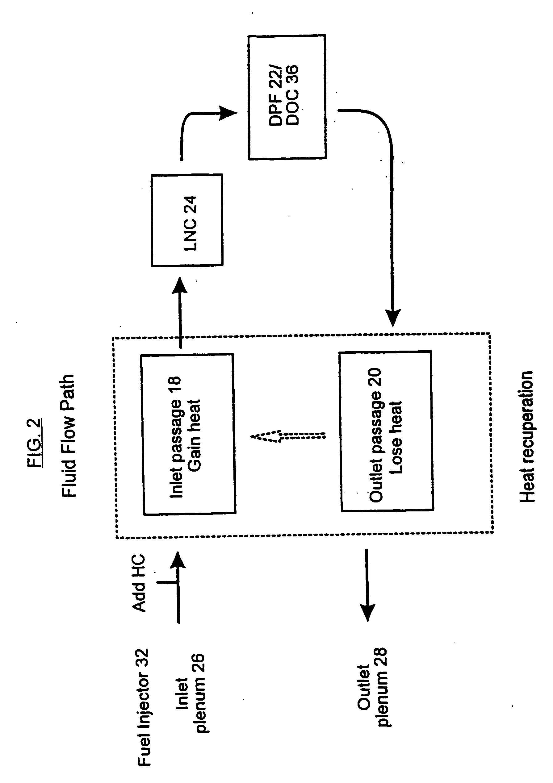
[0030] Within the shell are two exchanger walls 14 and 16 that form an inlet passage 18 and an outlet passage 20 for heat exchange between the entering and exiting fluid stream. The exchanger walls allow heat transfer across their surfaces, and can receive normal lean-burn exhaust flows without excess corrosion. The exchanger walls form a spiral structure, in which heat exchanges between the pre-and post-treatment streams in an inward spiral flow path and an outward spiral flow path. The exch...


PUM


Abstract

An apparatus and method to treat fluid streams, and in particular emissions from lean-burn engines such as diesel engines, are disclosed, which use multiple catalysts chosen to remove hydrocarbons, carbon monoxide, particulate matter, and oxides of nitrogen. The apparatus and method also provide for heat exchange between the inlet and outlet exhaust streams to sustain the catalyzed reactions, by placing the catalysts in the temperature zones where their operation is enhanced, and they also allow for regeneration of a filter used to trap particulate matter in the streams.

Description

RELATED APPLICATION INFORMATION [0001] This patent is a continuation of application Ser. No. 09 / 831,207 filed on Feb. 6, 2002 the disclosure of which is incorporated herein by reference, which is a 35 U.S.C. § 371 application of PCT / US99 / 26050 filed on Nov. 4, 1999 the disclosure of which is incorporated herein by reference, which is a continuation of Application Ser. No. 60 / 107,482 filed on Nov. 6, 1998 the disclosure of which is incorporated herein by reference.NOTICE OF COPYRIGHTS AND TRADE DRESS [0002] A portion of the disclosure of this patent document contains material which is subject to copyright protection. This patent document may show and / or describe matter which is or may become trade dress of the owner. The copyright and trade dress owner has no objection to the facsimile reproduction by any one of the patent disclosure as it appears in the Patent and Trademark Office patent files or records, but otherwise reserves all copyright and trade dress rights whatsoever. BACKGR...

Claims


Application Information

Patent Timeline
Patent Type & Authority Applications(United States)
IPC IPC(8): B01D53/94F01N3/00F01N3/025F01N3/035F01N3/10F01N3/20F01N13/02
CPCB01D53/944B01D53/9454B01D2258/012F01N3/0253F01N3/035F01N13/0097F01N2240/02F01N2260/08F01N2610/03Y02T10/22Y02T10/24F01N3/2066Y02A50/20Y02T10/12
Inventor PAGE, DORRIAH L.EDGAR, BRADLEY L.MACDONALD, ROBERT J.
Owner PAGE DORRIAH L
Why Eureka
Try Eureka