
Heat sink and method for making same

a heat sink and heat sink technology, applied in the direction of basic electric elements, semiconductor devices, lighting and heating apparatus, etc., can solve the problems of poor heat transfer efficiency, poor thermal conductivity, and high heat generation of electronic components, so as to reduce the thermal resistance between the base and the fins, improve heat transfer efficiency, and improve the effect of heat transfer efficiency

Inactive Publication Date: 2005-11-17
HON HAI PRECISION IND CO LTD
View PDF11 Cites 12 Cited by
  • Summary
  • Abstract
  • Description
  • Claims
  • Application Information

AI Technical Summary

Benefits of technology

[0008] Accordingly, an object of the present invention is to provide a heat sink which has relatively low thermal resistance between a base and fins thereof.
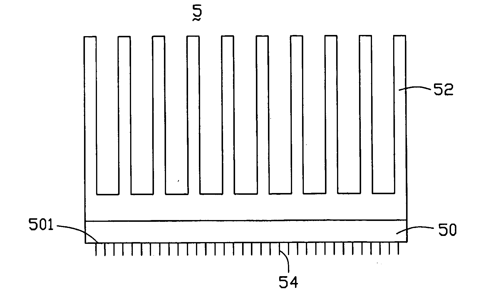
[0012] In a preferred embodiment, the base and fins are made from a same sintered metallic nano-powder. Alternatively, the base and the fins are made from two different sintered metallic nano-powders. The metallic nano-powder is selected from the group consisting of gold, silver, copper, aluminum, and any alloy thereof. A grain size of the metallic nano-powder is in the range from 1 to 99 nanometers. Preferably, the heat sink further comprises nanomaterials such as carbon nanotubes, carbon nanotcapsules. The nanomaterials are attached on a bottom surface of the base, for improving the heat exchange performance of the heat sink.
[0015] Since the heat sink of the present invention is integrally formed by sintering, any thermal resistance between the base and the fins is minimized. In addition, because the base and the fins of the heat sink are all made from metallic nano-powders having good thermal conductivity, a surface area of the heat sink is larger than that of a comparable heat sink made by extrusion. Therefore, a heat transfer efficiency of the heat sink is improved.

Problems solved by technology

When the electronic device operates, the electronic components can generate much heat.
The heat must be removed from the electronic components; otherwise the electronic device may malfunction or even be damaged or destroyed.
If the electronic component operates above its threshold operating temperature, it is liable to operate poorly or improperly.
The process of extrusion necessarily limits the size and surface area of the fins.
Therefore, the amount of heat that the heat sink can remove from the electronic component is limited.
However, the soldering process is relatively complicated and time-consuming.
As a result, the heat transfer efficiency of the heat sink assembly is relatively low.

Method used


Image

  • Heat sink and method for making same
  • Heat sink and method for making same

Examples


Embodiment Construction

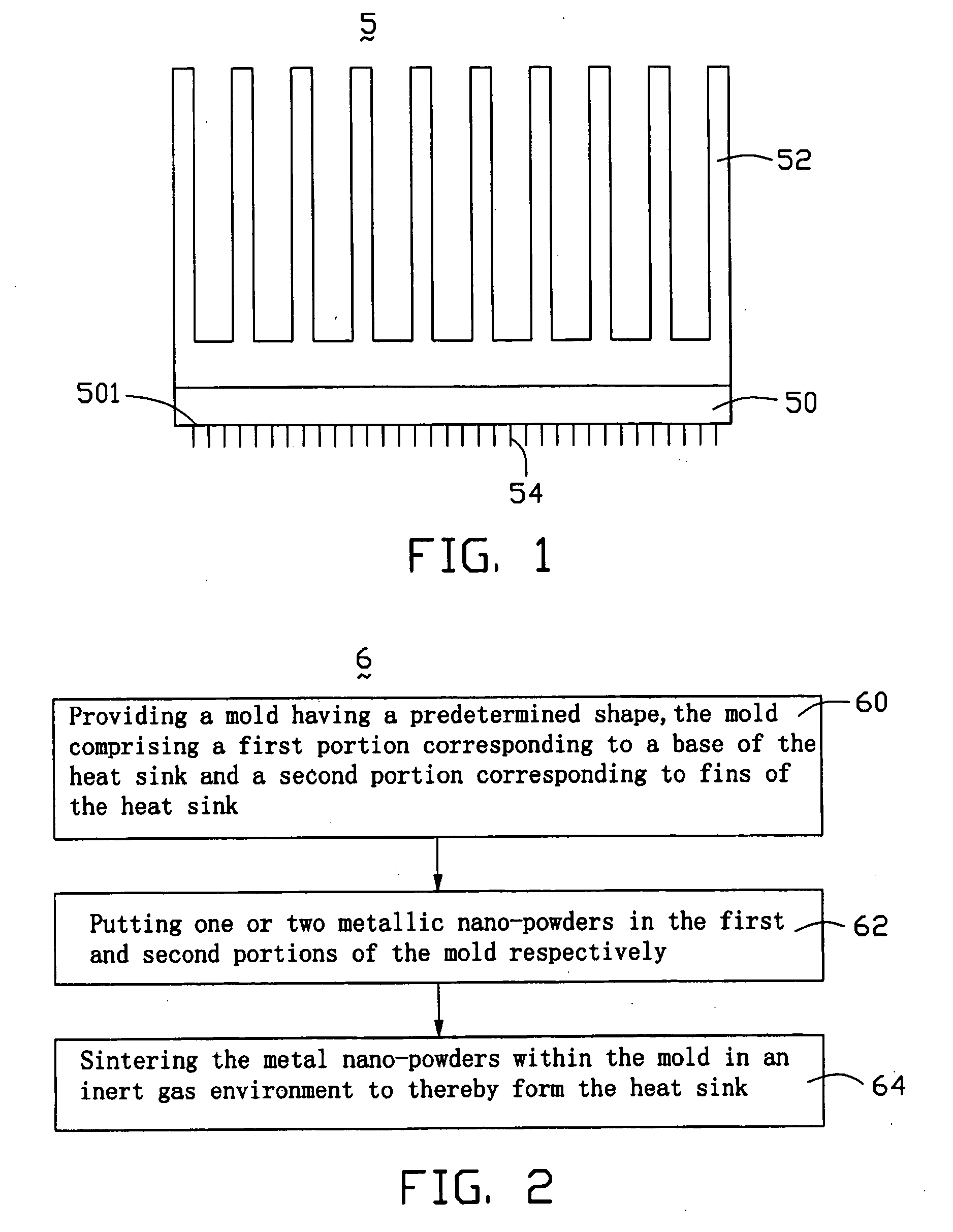
[0019] Referring to FIG. 1, a heat sink 5 as a heat dissipating device for dissipating heat from an electronic component in accordance with the present invention comprises a base 50, and a plurality of fins 52 formed on the base 50.

[0020] The base 50 and the fins 52 are formed integrally by sintering one or two metallic nano-powders. Preferably, the base 50 and the fins 52 are made from a same metallic nano-powder. Alternatively, the base 50 and the plurality of fins 52 are made from different metallic nano-powders. The metallic nano-powder is selected from the group consisting of gold, silver, copper, aluminum, and any alloy thereof. A grain size of the metallic nano-powder is preferably in the range from 1 to 99 nanometers. Preferably, the heat sink 5 further comprises nanomaterials such as carbon nanotubes 54 or carbon nanocapsules attached thereon, for improving the heat exchange performance of the heat sink 5. More preferably, the nanomaterials are carbon nanotubes 54, which a...


PUM


Abstract

A heat sink (5) for dissipating heat from an electronic component includes a base (50), and a plurality of fins (52) formed on the base. The base and the plurality of fins are integrally formed by sintering one or two metallic nano-powders. Since the heat sink is integrally formed by sintering, any thermal resistance between the base and the fins is minimized. In addition, because the base and the fins of the heat sink are all made from one or more metallic nano-powders having good thermal conductivity, a surface area of the heat sink is larger than that of a comparable heat sink made by extrusion. Therefore, a heat transfer efficiency of the heat sink is improved.

Description

TECHNICAL FIELD [0001] The present invention relates to heat sinks and methods for making the same, and more particularly to a heat sink using nanomaterials and a method for making the same. BACKGROUND [0002] Numerous modern electronic devices, such as computers, comprise electronic components mounted on circuit boards. When the electronic device operates, the electronic components can generate much heat. The heat must be removed from the electronic components; otherwise the electronic device may malfunction or even be damaged or destroyed. [0003] Most electronic components are designed to operate over a wide range of temperatures. If the electronic component operates above its threshold operating temperature, it is liable to operate poorly or improperly. For example, the electronic component may operate too slowly, be less tolerant of voltage variations, be less tolerant of electrical “noise,” or fail prematurely. [0004] One technique for removing heat is to a employ a heat sink as...

Claims


Application Information

Patent Timeline
IPC IPC(8): F28F7/00H01L23/373
CPCB82Y10/00H01L23/373H01L23/3733H01L23/3736H01L2924/0002H01L2924/00
Inventor LEU, CHARLESYU, TAI-CHERNGCHEN, GA-LANE
Owner HON HAI PRECISION IND CO LTD
Learn More