Snowmobile

a technology of snowmobiles and wheels, applied in the field of snowmobiles, can solve the problems of difficult to achieve optimal positioning of the foot, and achieve the effect of good foot holding property and excellent turning performan

Inactive Publication Date: 2005-11-17
HONDA MOTOR CO LTD
View PDF19 Cites 18 Cited by
  • Summary
  • Abstract
  • Description
  • Claims
  • Application Information

AI Technical Summary

Benefits of technology

[0015] One of the objects of the present invention is to provide a snowmobile in which a silencer can be disposed close to an engine and which is excellent in turning performance. A further object of the present invention is to provide a snowmobile comprising step floors good in foot holding property.

Problems solved by technology

However, since the step floor as a whole is a wide and flat structure, and leaves a room for improvement, for example, there is the problem that the optimum positioning of the foot is difficult to achieve when the rider rides in a standing pose.

Method used


Image

  • Snowmobile
  • Snowmobile
  • Snowmobile

Examples


first embodiment

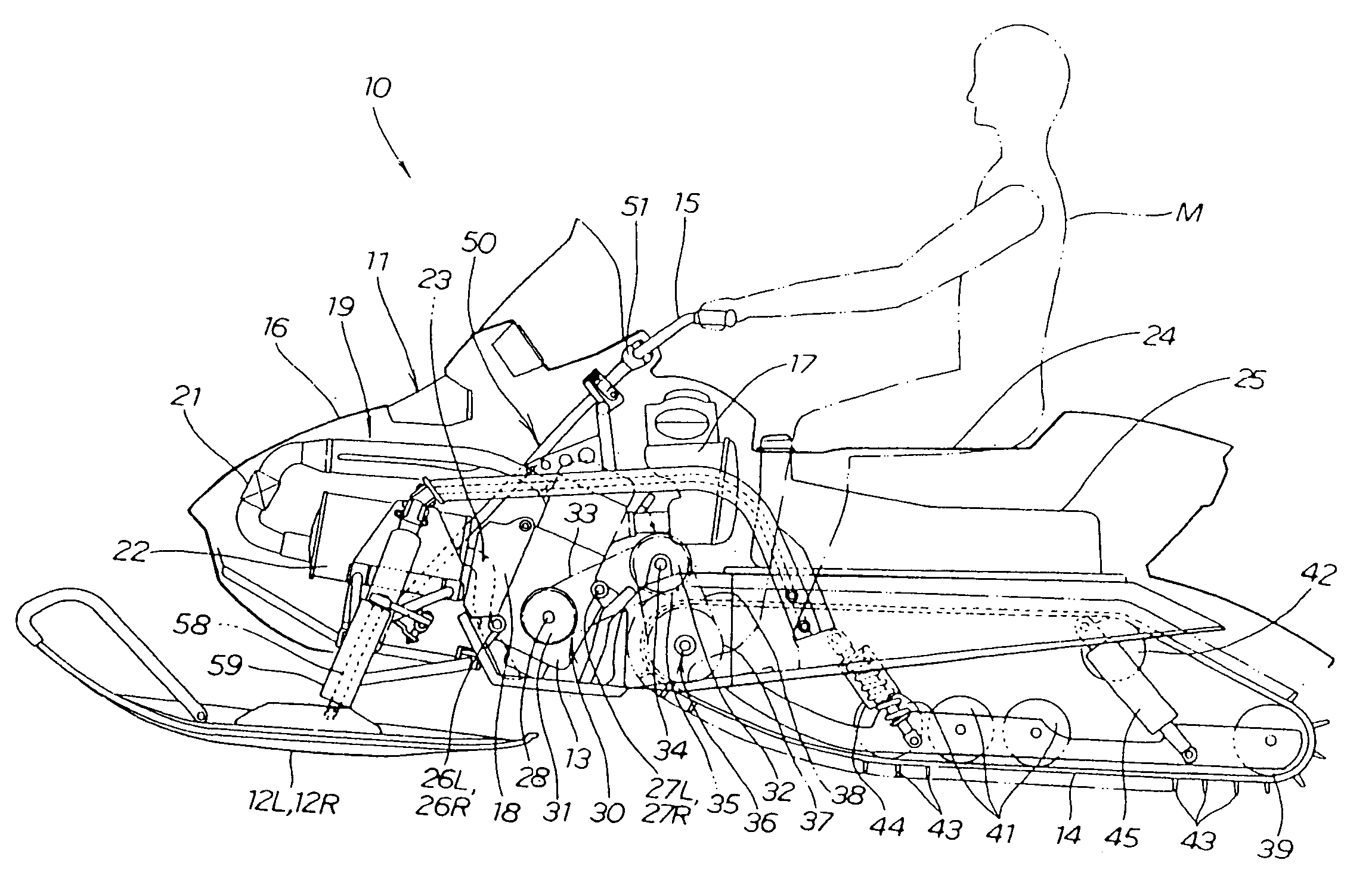
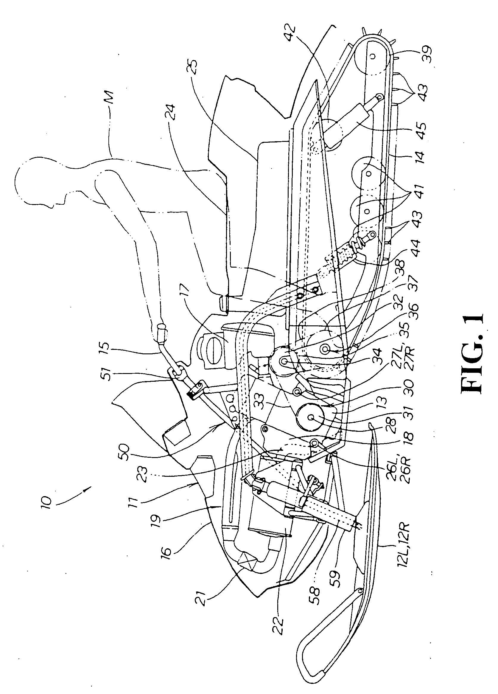
[0059]FIG. 1 is an overall side view of a snowmobile according to the present invention. The snowmobile 10 is a snow vehicle which comprises a left-right pair of skis 12L, 12R (12R is behind 12L, here and hereinafter), an engine 13 and a track belt 14 in this order from the front side toward the rear side of a vehicle body 11, which is made to run by driving the track belt 14 by the power of the engine 13, and in which the skis 12L, 12R can be steered by operating a steering handle 15.

[0060] A seat 24 on which to seat the rider is provided on the rear side of the engine 13 provided at a front portion of the vehicle body, and a fuel tank 25 is provided on the lower side of the seat 24 in the state of being elongate in the front-rear direction.

[0061] Symbols M denotes the rider, 16 denotes a vehicle body cover, 17 denotes an air cleaner, 18 denotes an oil tank, 19 denotes an exhaust pipe, 21 denotes a catalyst, 22 denotes a silencer, and 23 denotes a tail pipe. Incidentally, the conf...

second embodiment

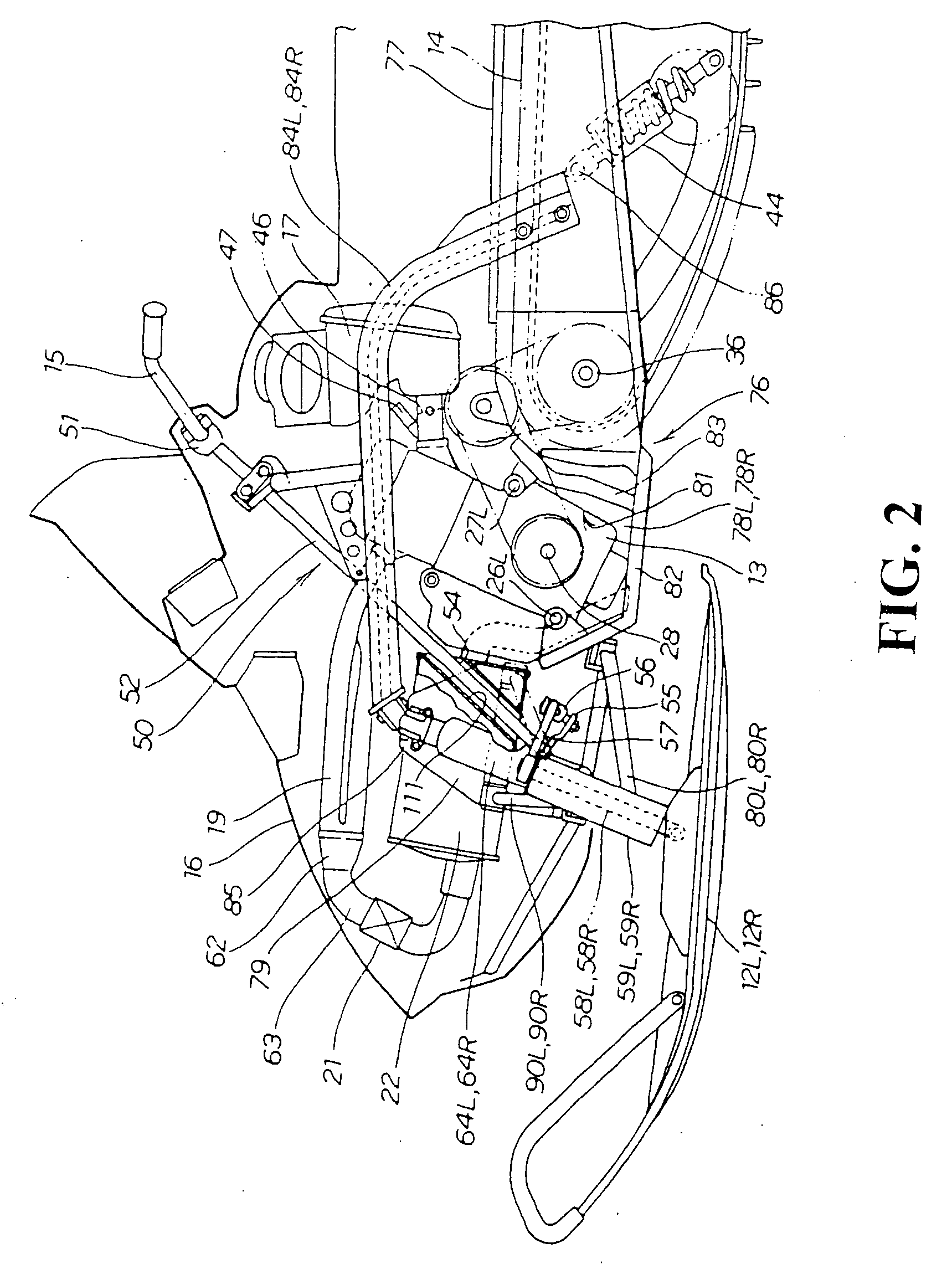
[0104]FIG. 4 is a side view of a front portion of a snowmobile according to the present invention, and is different from FIG. 2 in that the silencer 22 is provided with a recessed portion 112 as a substitute for the through-hole, and the steering shaft lower portion 54 is passed through the recessed portion 112.

[0105] Since the silencer 22 is provided with the recessed portion 112 through which to pass the steering shaft 50, the steering shaft 50 can be laid out without any interference between the silencer 22 and the steering shaft 50.

[0106] In addition, in the case of laying out the steering shaft 50, limitations as to the angle and position in laying out the steering shaft 50 can be reduced.

[0107] As a result, the steering shaft 50 can be easily laid out in the limited internal space of the snowmobile.

third embodiment

[0108]FIG. 5 is a side view of a front portion of a snowmobile according to the present invention, and is different from FIG. 2 in that the steering shaft 50 is composed of a steering shaft upper portion 52 provided at its upper end with a steering handle holder 51 and inclined forwardly downwards, a universal joint 53 mounted to the lower end of the steering shaft upper portion 52, and a steering shaft lower portion 54 extended substantially vertically downwards from the universal joint 53. In other words, the universal joint 53 is added between the steering shaft upper portion 52 and the steering shaft lower portion 54.

[0109] Since the steering shaft 50 is formed to be bendable through the universal joint 53, the layout of the steering shaft 50 can be modified flexibly.

[0110] Since the layout of the steering shaft 50 can be modified flexibly, the position of the steering handle 15 connected to the steering shaft 50 can be set to an optimum position according to the physique and t...


PUM


Abstract

A snowmobile provided with skis and being steerable by a steering shaft, and being provided with a silencer on the front side of an engine. The steering shaft passes between the engine and the silencer and overlaps the silencer in side view. Flat step floors for a rider's feet are provided on lateral sides of a lower portion of a seat. Step bars for enabling positioning of the rider's feet are provided at front portions of the step floors. The step bars are each provided on the rear side relative to the step floor tip end and within 350 mm from a track belt drive shaft which is provided on the rear side of the engine. The resulting configuration of the snowmobile makes it possible to lay out the silencer close to the engine, affords excellent turning performance, and provides step floors for good foot holding properties.

Description

CROSS-REFERENCE TO RELATED APPLICATION [0001] The present application claims priority under 35 U.S.C. §119 to Japanese Patent Application Nos. 2004-146749 and 2004-146722, filed May 17, 2004, the entire contents of which are hereby incorporated by reference. BACKGROUND OF THE INVENTION [0002] 1. Field of the Invention [0003] The present invention relates to a snowmobile capable of running on a snow field, with an engine as a drive source. [0004] 2. Description of Background Art [0005] There have been made a variety of proposals as to the layout of apparatuses around an engine (the layout of a steering shaft and a silencer) in a snowmobile running by the power of the engine. See, for example Japanese Patent Laid-open No. Hei 7-228288. [0006] FIG. 2 of Japanese Patent Laid-open No. Hei 7-228288 is a plan view showing the internal structure of a conventional snowmobile, in which symbol 1 denotes the snowmobile, symbol 14 denotes an engine, symbol 21 denotes a silencer, symbol 24 denote...

Claims


Application Information

Patent Timeline
Patent Type & Authority Applications(United States)
IPC IPC(8): B62D55/07B62J25/00B62K11/12B62K21/00B62M27/02F01N13/08
CPCB62M27/02B62K21/00
Inventor ABE, TOMOHISAYAMADA, KOZO
Owner HONDA MOTOR CO LTD
Why Eureka
Try Eureka