Rolling bearing lubricating method and device

a lubricating method and rolling bearing technology, applied in the direction of lubricant transfer, positive displacement liquid engine, pump, etc., can solve the problems of lowering the ability of lubricant oil to form an oil film, difficult for lubricant oil to be lubricated, and increasing the temperature of the bearing

Active Publication Date: 2005-11-17
NTN CORP
View PDF5 Cites 20 Cited by
  • Summary
  • Abstract
  • Description
  • Claims
  • Application Information

AI Technical Summary

Benefits of technology

[0051] Where the cylindrical roller bearing with its inner race having a collar is employed for the rear bearing of the spindle device, the contact pressure at an area of contact between a front collar in the rear bearing and an adjacent roller end face will increase under the influence of thermal expansion of the spindle caused by heat developed during the operation of the bearing, resulting in a disadvantage condition of the sliding friction between the collar and the roller end faces. Because of this, the air/oil lubricating structure according to the thi

Problems solved by technology

However, during the high speed rotation, the bearing temperature tends to increase, accompanied by lowering the capability of the lubricant oil to form an oil film.
Therefore, the higher the rotational speed, the more severe the lubricating condition, making it difficult for the lubricant oil, jetted from the nozzle 156, to get trapped inside the bearing 133.
On the other hand, during the low speed rotation, the bearing temperature is low and the capability of forming the air curtain which hampers the supply of the lubricant oil internally into the bearing is also low.
However, the above discussed suggestion has not led to disclosure of a specific angle of inclination appropriate for the inclined surface area of the inner race employed in the rolling bearing.
Separation of the air/oil mixture away from halfway the inclined surface area of the bearing inner race leads to the incapability of the air/oil mixture efficiently reaching the rolling elements, resulting in lack of a sufficient amount of the lubricant oil.
In such case, although it may be suspected that if the respective amounts of air and lubricant oil, both forming the air/oil mixture, are incre

Method used


Image

  • Rolling bearing lubricating method and device
  • Rolling bearing lubricating method and device
  • Rolling bearing lubricating method and device

Examples


first embodiment

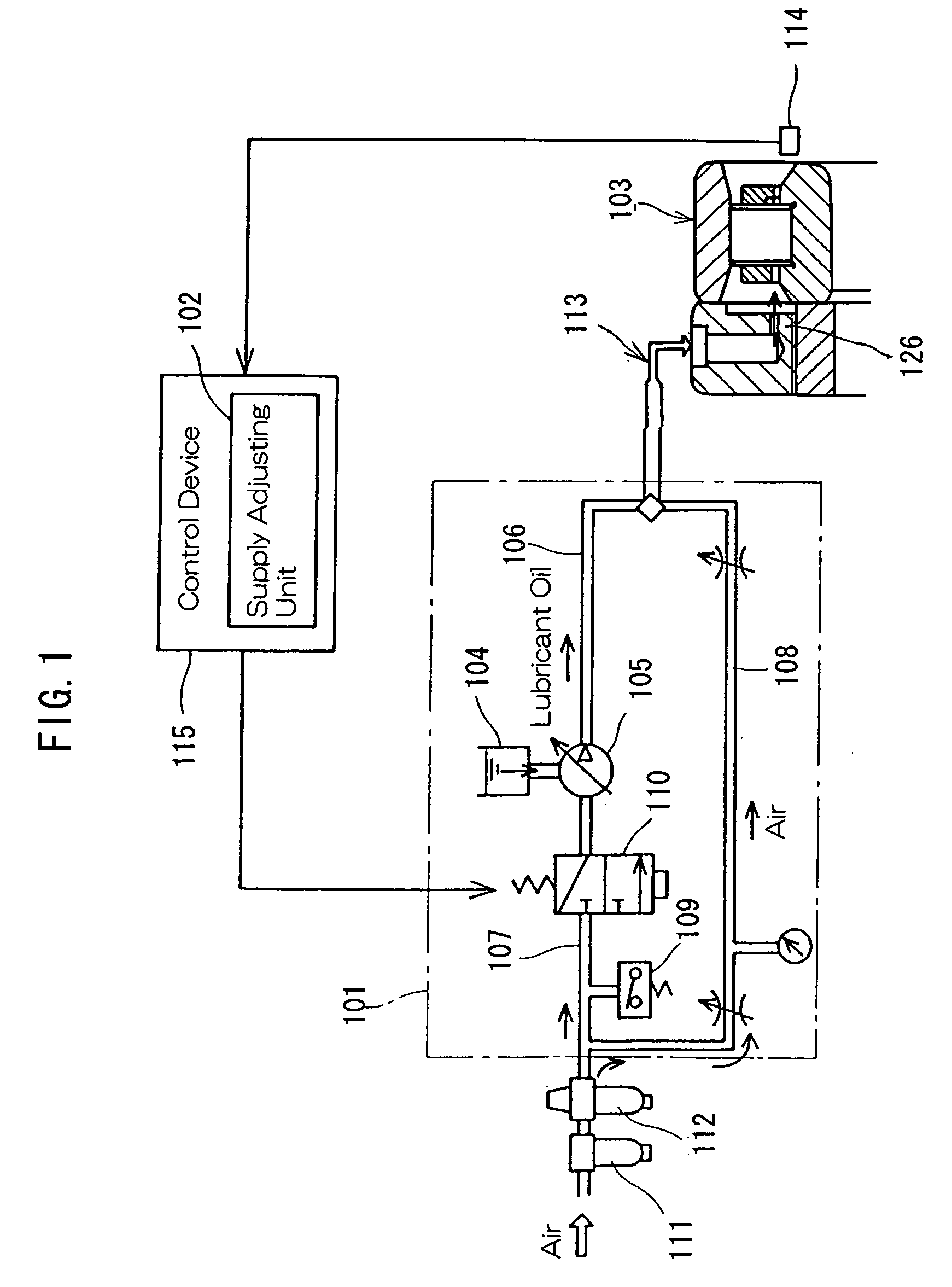
[0096] Hereinafter, the lubricating method for the rolling bearing assembly according to the present invention, which utilizes the lubricating device of the structure described above, will be described. During the operation of the rolling bearing assembly 103, the rotational speed of the inner race of the rolling bearing assembly 103 is monitored by the rotational speed detecting unit 114. The information signal indicative of the rotational speed detected by the rotational speed detecting unit 114 is compared by the supply adjusting unit 102 with a predetermined speed (r.p.m) dividing the rotational speed regions, and the supply adjusting unit 102 subsequently outputs a signal indicative of the preset supply amount for the corresponding speed region. This signal is used for causing the solenoid valve 110 to be brought in an opened position and the interval of this signal represents the interval of supply of the air / oil mixture from the nozzle 106.

[0097] The supply adjusting unit 102...

third embodiment

[0149]FIGS. 16 and 17 illustrate air / oil lubricating structures for the rolling bearing assembly according to fifth and sixth preferred embodiments of the present invention, respectively. Those embodiments are substantially similar to the previously described third embodiment of FIG. 14, except that in those embodiments of FIGS. 16 and 17, the retainers 5A (FIG. 14) employed in the cylindrical roller bearing 1A are replaced with a comb-shaped retainer 5B. While the retainer 5A employed in the example shown in FIG. 14 is of a cage type designed to have pockets each embracing the corresponding rolling element 4A in the form of a cylindrical roller, the comb-shaped retainer 5B has pockets each designed to encompass the corresponding rolling element 4A in the form of a cylindrical roller from three directions while opening in one direction. Because of this, a generally ring-shaped guide side plate 19 adjoining an end face of a cylindrical portion of the comb-shaped retainer 5B is fixed ...

second embodiment

[0152] Other structural features of each of the embodiments shown in and described with particular reference to FIGS. 16 and 17, respectively, are substantially similar to those in the second embodiment shown in and described with particular reference to FIG. 9.

[0153]FIG. 18 illustrates an air / oil lubricating structure for the rolling bearing assembly according to a seventh preferred embodiment of the present invention. In this embodiment, the discharge passage 8 defined in the nozzle member 6A is so positioned that the air / oil mixture can be jetted into the discharge groove 7 in a direction parallel to the axial direction of the rolling bearing 1. The discharge groove 7 have side faces facing the discharge passage 8, which are formed as an inclined surface so that the air / oil mixture jetted can be guided towards the inclined surface area 2b of the inner race 2. The nozzle member 6A is fitted directly to the inner peripheral surface of the housing 9 and concurrently serves as an out...


PUM

PropertyMeasurementUnit
Temperatureaaaaaaaaaa
Angleaaaaaaaaaa
Diameteraaaaaaaaaa

Abstract

There is provided a lubricating method for a rolling bearing assembly capable of achieving a reliable lubrication and exhibiting a stable temperature rise. The method is for supplying a lubricant oil to the rolling bearing assembly during the operation thereof, in which in order to keep the temperature of a rolling bearing assembly (103) within a predetermined tolerance, the amount of the lubricant oil to be supplied during the operation is automatically or manually adjusted by means of a supply adjusting unit (102). Supply of the lubricant oil is performed in the form of an air/oil mixture by the use of a lubricant supply unit (101). The amount of the lubricant oil supplied varies depending on the rotational speed of the rolling bearing assembly (103). Change of the amount of the lubricant oil supplied depending on the rotational speed of the rolling bearing assembly (103) is carried out based on a result of sampling of data showing increase in temperature of the rolling bearing assembly (103) depending on the rotational speed thereof under a plurality of different lubricating conditions in which a different amount of the lubricant oil to be supplied is employed.

Description

FIELD OF THE INVENTION [0001] The present invention relates to a lubricating method, a lubricating device and an air / oil lubricating structure for lubricating a rolling bearing assembly such as used in supporting a spindle of the machine tool or a ball screw mechanism (a ball and nut drive mechanism), and also to a spindle device utilizing the air / oil lubricating structure. BACKGROUND ART [0002] The purpose of lubricating rolling bearings is to prevent metallic rolling elements from directly contacting metallic inner and outer races of the rolling bearings by forming a thin oil film on rolling surfaces and sliding surfaces thereof. Lubrication when effected to the rolling bearings brings about the following merits: [0003] (1) Minimization of friction and frictional wear, [0004] (2) Removal of heat evolved as a result of friction, [0005] (3) Increase of the lifetime of the rolling bearings, [0006] (4) Prevention of rusting, and [0007] (5) Prevention of foreign matter from being trapp...

Claims


Application Information

Patent Timeline
IPC IPC(8): B23Q1/40B23Q11/12B23Q11/14F16C19/16F16C19/24F16C19/26F16C19/36F16C33/58F16C33/66F16N7/32F16N29/02F16N37/00
CPCB23Q11/122B23Q11/123B23Q11/124F16C19/163F16C19/26F16C33/58F16C2240/02F16C33/667F16C33/6674F16N7/32F16N29/02F16N37/003F16N2250/16F16C33/6662F16C19/546F16C2322/39B23Q1/38B23Q11/12F16C33/66
Inventor KOSUGI, FUTOSHIMORI, MASATSUGUUEDA, KEIICHI
Owner NTN CORP
Why Eureka
Try Eureka