Illumination optical system, exposure device using the illumination optical system, and exposure method

an illumination optical system and optical system technology, applied in optics, printing, instruments, etc., can solve the problems of deteriorating image quality, inevitably growing in size, and difficult physical layout of such a device, and achieve the effect of shortening the overall length of the devi

Inactive Publication Date: 2005-11-17
FUJIFILM CORP
View PDF4 Cites 2 Cited by
  • Summary
  • Abstract
  • Description
  • Claims
  • Application Information

AI Technical Summary

Benefits of technology

[0010] In consideration of the foregoing circumstances, the object of the present invention is to provide an illumination optical system using an optical integrator, which is capable of shortening the overall length thereof.
[0011] Moreover, the object of the present invention is to provide an exposure method and an exposure device which can be miniaturized by applying an illumination optical system as described above.
[0019] Moreover, in the illumination optical system of the present invention, if, in a particular case where the Etendue of the light source is set small, for example, to 1 mm2·str or less, a numerical aperture NA at the illuminated side (hereinafter referred to as illumination NA) can be reduced without a decrease in illumination efficiency. Thus, the focal depth of the optical system set at the further side of the illuminated body can be enlarged, and the laser beam can be narrowed. In this case, problems, such as the exposed image formed by the imaging optical system set at the further side of the illuminated body becoming out of focus can be prevented, for example, when the illumination optical system is applied to the exposure device.
[0033] On the other hand, in the case of using, the foregoing fiber light source, the light source side Etendue Es is 0.06 mm2·str, and the illumination NA becomes extremely small, approximately 0.01, and the focal depth of the imaging lens becomes large. Thus, the foregoing problem of focusing can be prevented.

Problems solved by technology

In the case that the conventional illumination optical system was applied to an exposure device in which, unlike a magnifying projecting device, photosensitive materials were exposed by light magnified at a 1:1 magnification ratio or less, the focal depth was too small, thereby deteriorating image quality.
Thus, a problem has been recognized that an exposure device and the like to which this illumination optical system is applied has inevitably grown in size, and that physical layout of such a device is difficult.

Method used


Image

  • Illumination optical system, exposure device using the illumination optical system, and exposure method
  • Illumination optical system, exposure device using the illumination optical system, and exposure method
  • Illumination optical system, exposure device using the illumination optical system, and exposure method

Examples


Embodiment Construction

[0042] With reference to the drawings, embodiments of the present invention will be described below.

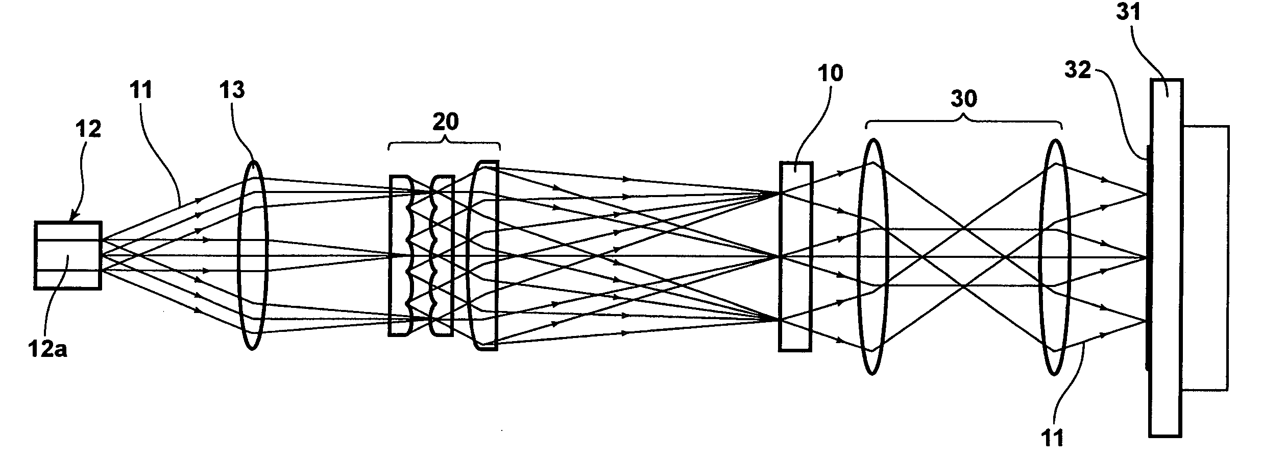
[0043]FIG. 4 shows a schematic constitution of an illumination optical system according to one embodiment of the present invention. This illumination optical system includes: a light source 12 which irradiates illumination light 11 onto a two-dimensional spatial light modulator (SLM) 10 which is an illuminated body; a collimator lens 13 which converts the illumination light 11 emitted in a state of diverging rays from this light source 12 into parallel rays; and an optical integrator 20 which is placed between this collimator lens 13 and the two-dimensional SLM 10 and uniformizes the intensity distribution of the illumination light 11 by passing the light through optical elements.

[0044] In this embodiment, as the foregoing light source 12, a fiber light source is used which performs multiplexing of a plurality of lasers by making a plurality of lasers incident to an optical fiber an...


PUM


Abstract

In an illumination optical system constituted to uniformize the intensity distribution of illumination light by use of an optical integrator, the overall length thereof is shortened. The illumination optical system includes: a light source including a laser irradiating illumination light on an illuminated body such as a two-dimensional SLM and an optical integrator; the optical integrator being placed between this light source and the illuminated body and uniformizes the intensity distribution of the illumination light by passing the light through minute cells. In this system, the size of the minute cell of the optical integrator (S1=S2) is 1.5 mm or less.

Description

BACKGROUND OF THE INVENTION [0001] 1. Field of the Invention [0002] The present invention relates to an illumination optical system, particularly in detail to an illumination optical system which passes illumination light emitted from a laser through an optical integrator and uniformizes its intensity distribution. [0003] Moreover, the present invention relates to an exposure method and device which exposes a photosensitive material by irradiating illumination light, modulated after being emitted from an illumination optical system as described above, onto the photosensitive material. [0004] 2. Description of the Related Art [0005] Exposure devices designed to illuminate a two-dimensional spatial light modulator, such as a liquid crystal display (LCD) and a digital micromirror device (DMD), with light from a light source and light modulated by this spatial light modulator to expose photosensitive material, are known. Devices of this type are required to illuminate the spatial light ...

Claims


Application Information

Patent Timeline
Patent Type & Authority Applications(United States)
IPC IPC(8): G02B27/09
CPCG02B27/09
Inventor OHMORI, TOSHIHIKOISHIKAWA, HIROMI
Owner FUJIFILM CORP
Why Eureka
Try Eureka