
Image forming system

Inactive Publication Date: 2005-11-17
RICOH KK
View PDF35 Cites 25 Cited by
  • Summary
  • Abstract
  • Description
  • Claims
  • Application Information

AI Technical Summary

Benefits of technology

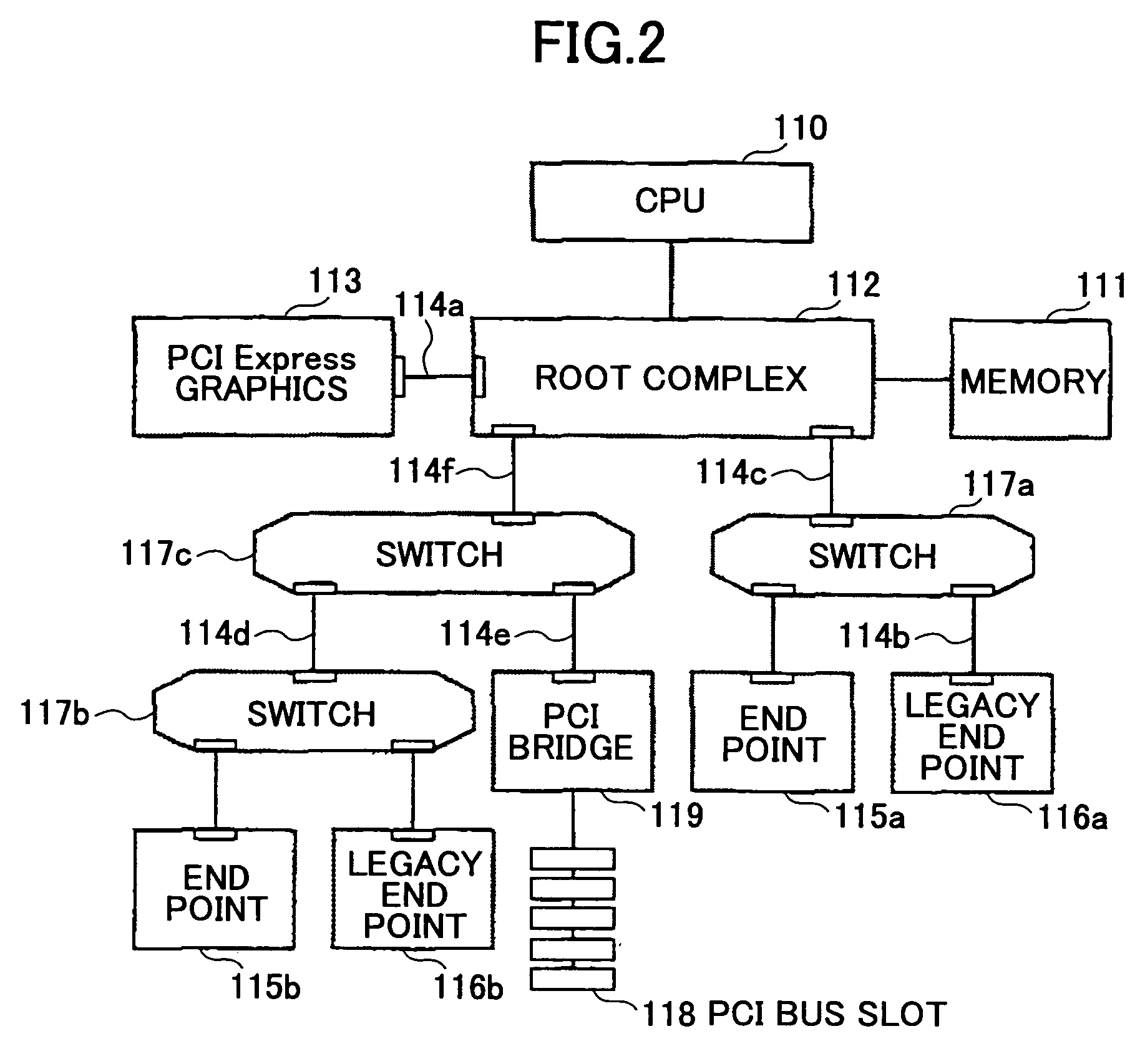
[0019] Another and more specific object of the present invention is to provide an image forming system which can further improve the high-speed operation and the extensibility, by applying an interface technology such as the PCI Express to the image forming system.
[0020] Still another and more specific object of the present invention is to provide an image forming system which enables a high-speed image data output and simultaneous transfer, even when timing restrictions of the line synchronous transfer exist, by effectively utilizing a high-speed serial bus such as the PCI express standard that realizes a high scalability.
[0021] A further object of the present invention is to provide an image forming system comprising a serial communication control part, an image input part, an image output part, an image processing part, a storage part and a printer controller; and a high-speed serial bus mutually coupling the serial communication control part and at least one of the image input part, the image output part, the image processing part, the storage part and the printer controller. According to the image forming system of the present invention, it is possible to further improve the high-speed operation and the extensibility, by applying an interface technology such as the PCI Express to the image forming system. Further, by transferring image data in synchronism with a line synchronizing signal via the high-speed serial bus, it is possible to realize a high-speed image data output and simultaneous transfer, even when timing restrictions of the line synchronous transfer exist, by effectively utilizing a high-speed serial bus such as the PCI express standard that realizes a high scalability.

Problems solved by technology

Under this design concept, it is possible to design an inexpensive image forming system, but on the other hand, it is difficult to modify or expand the image forming system in a simple manner, thereby making the extensibility of the image forming system relatively poor.
Consequently, the developing cost and the developing time of the modified image forming system increase, to thereby deteriorate the extensibility of the image forming system.
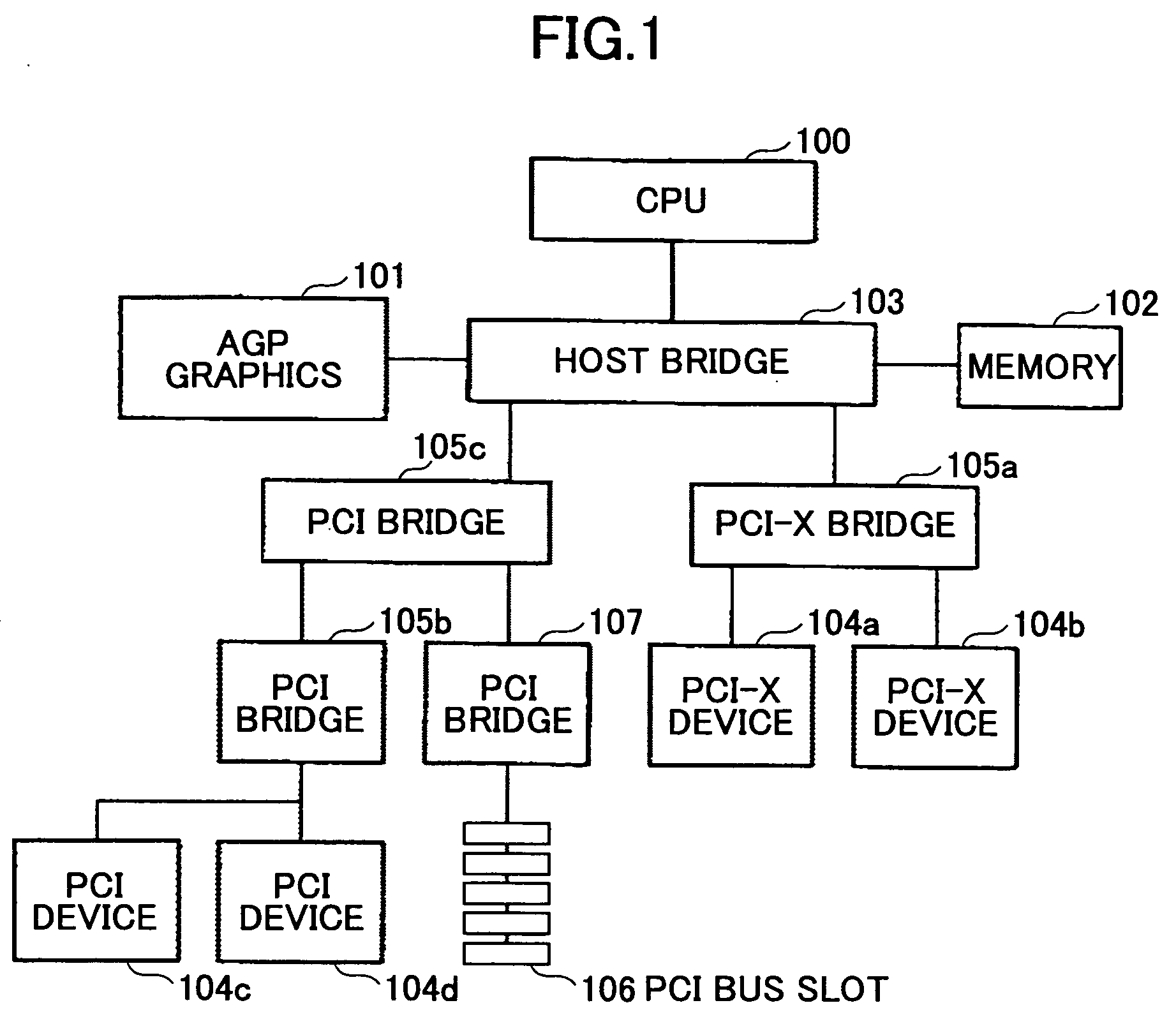
However, the PCI bus transfers the control data, the image data and the like in parallel, which consequently increases both the number of wirings and the cost of the interface.
As a result, the degree of layout freedom on the mother board is limited, and it is difficult to flexibly cope with the multiple functions.
Furthermore, when transferring the data in parallel, data error and inconsistency are generated among the signal lines, and the crosstalk phenomenon occurs in which the signal lines mutually affect voltages thereof.
Accordingly, the PCI bus is unsuited for high-speed data transfer, and it is difficult to satisfy the demands of the high-speed operation when using the PCI bus.
In other words, according to the PCI bus employing the parallel system, problems such as racing and skew are generated, and the transfer rate that is obtainable is now becoming too low for use in the image forming system which must further improve the high-speed operation and high image quality.
That is, the data transfer must be made time-divisionally between the modules, and it is difficult to realize a high-speed data transfer.
However, since there are demands to further improve the high-speed operation and the high image quality, it is becoming more difficult to carry out the data transfer at a sufficiently high speed that is demanded by employing the structure proposed in the Japanese Laid-Open Patent Application No.2001-016382 using the general-purpose bus such as the IEEE1394 and, the USB.
In addition, it is becoming more difficult to secure the desired extensibility of the digital copying apparatus due to electrical and physical restrictions on the hardware.
Moreover, when measures are taken to secure the high-speed data transfer and the extensibility, the bus width increases to generate problems such as difficulty in designing the circuit board, increase in the cost of the circuit board, increase in the cost of the digital copying apparatus due to increased number of ASIC pins, and the like.

Method used

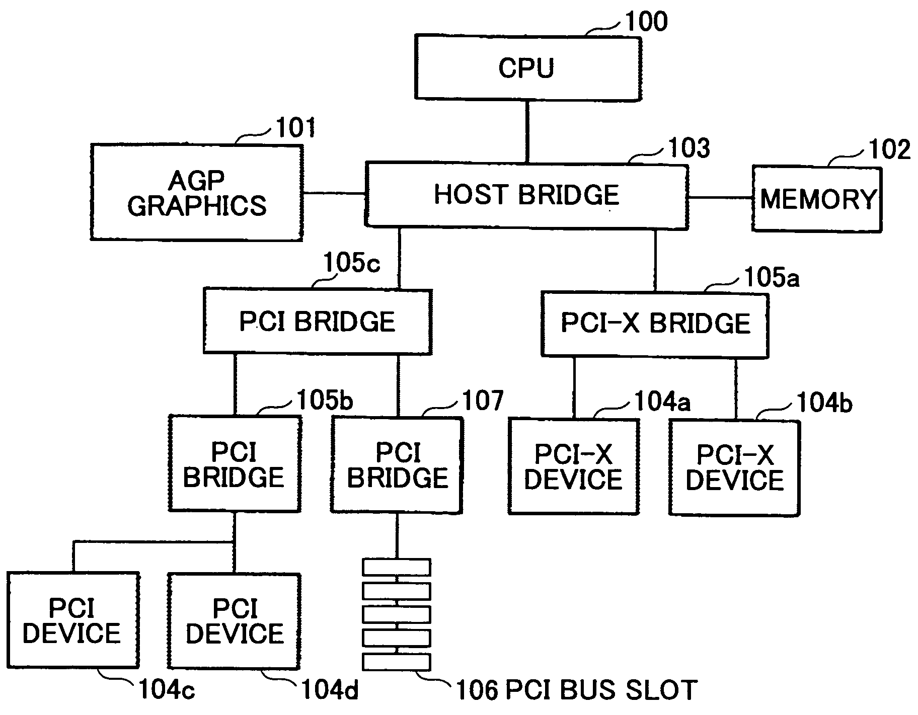

Image

  • Image forming system
  • Image forming system
  • Image forming system

Examples


Embodiment Construction

[0057] A description will be given of embodiments of an image forming system according to the present invention, by referring to the drawings.

Summary of PCI Express Standard

[0058] An embodiment of the image forming system according to the present invention utilizes the PCI Express (registered trademark) which is a high-speed serial bus. A summary of the PCI Express standard which is used as a precondition in this embodiment, will first be described based on an excerpt from Shoji Satomi, “Summary of PCI Express Standard”, Interface Magazine, pp.80-93, July 2003. In the following description, a high-speed serial bus refers to an interface which can exchange data at a high speed of 100 Mbps or higher by a serial transmission using a single transmission path.

[0059] The PCI Express, which corresponds to the standard that is to succeed the PCI bus system, is a bus that is standardized as a standard extension bus to be applied to computers in general. Generally, the PCI Express has feat...


PUM


Abstract

An image forming system comprising a serial communication control part, an image input part, an image output part, an image processing part, a storage part, a printer controller, and a high-speed serial bus. The high-speed serial bus mutually couples the serial communication control part and at least one of the image input part, the image output part, the image processing part, the storage part and the printer controller.

Description

BACKGROUND OF THE INVENTION [0001] 1. Field of the Invention [0002] The present invention generally relates to, and more particularly to image forming systems, and more particularly to an image forming system such as a composite apparatus and a Multi Function Peripheral (or Processor) (MFP) that treat various kinds of image data and carry out various kinds of processes. [0003] 2. Description of the Related Art [0004] A Japanese Laid-Open Patent Application No.2000-151878 proposes an architecture for a digital copying apparatus in which a plotter, a scanner and a user interface are connected to a processor via a standard bus such as a Peripheral Component Interconnect (PCI) bus. [0005] A Japanese Laid-Open Patent Application No.2001-016382 proposes a system structure for a digital copying apparatus provided with a scanner control part, a write control part and a main control part, in which a high-speed serial interface such as an IEEE1394 bus and a Universal Serial Bus (USB) is used ...

Claims


Application Information

Patent Timeline
IPC IPC(8): G06F15/00G09G5/02
CPCG06F3/13
Inventor OSHIKIRI, KOJISHINDOH, YASUYUKIIKEDA, JUNICHITAKEO, KOJITERAO, NORIYUKIOIZUMI, ATSUHIROMAITA, YUTAKANUMAKURA, SATORUSASAKI, TOHRU
Owner RICOH KK
Learn More