Fuel cell, separator unit kit for fuel cell, and fuel cell generating unit kit

a separator unit and fuel cell technology, applied in the direction of fuel cell details, cell components, electrochemical generators, etc., can solve the problem of not being able to independently set up how to change cross-sectional, and achieve the effect of high flow rate and easy machining

Inactive Publication Date: 2005-11-17
HITACHI LTD
View PDF1 Cites 23 Cited by
  • Summary
  • Abstract
  • Description
  • Claims
  • Application Information

AI Technical Summary

Benefits of technology

[0038] It is desirable that the closer to fluid outlet manifold, the smaller the pitch of the members is to make the fluid flow rate higher. It is also possible to adjust the pitch of the flow channel inlet portion opened on the manifold on the surface contacting the separator substrate of the frame to the pitch of the flow channel groove portion provided on the separator substrate. It is also possible to form the members provided on the frames, over the entire win

Problems solved by technology

Also, in the flow channel structure of the fuel cell disclosed in JP-A-2000-223137 has a problem that it is not possible to ind

Method used


Image

  • Fuel cell, separator unit kit for fuel cell, and fuel cell generating unit kit
  • Fuel cell, separator unit kit for fuel cell, and fuel cell generating unit kit
  • Fuel cell, separator unit kit for fuel cell, and fuel cell generating unit kit

Examples


embodiment 1

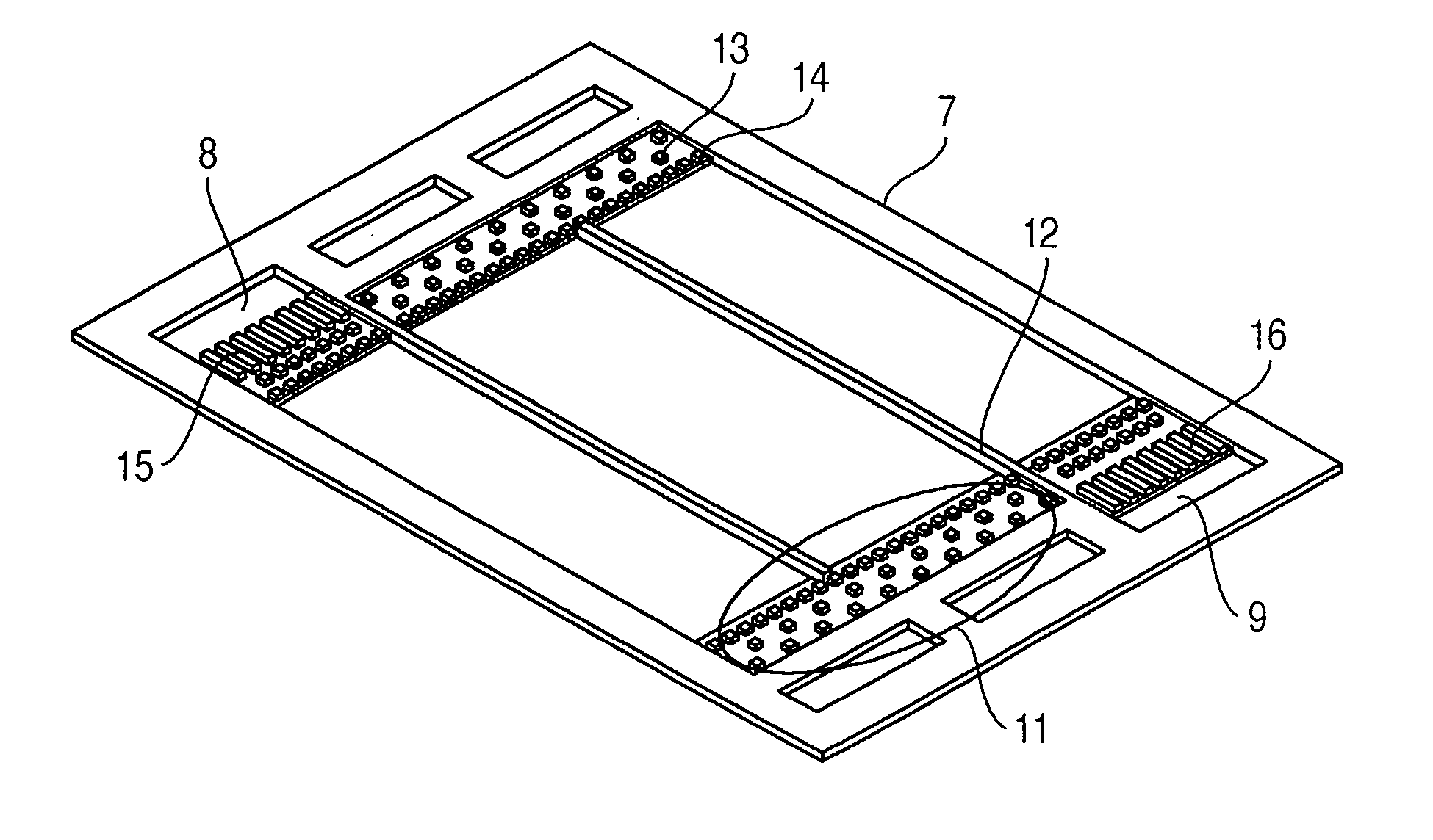
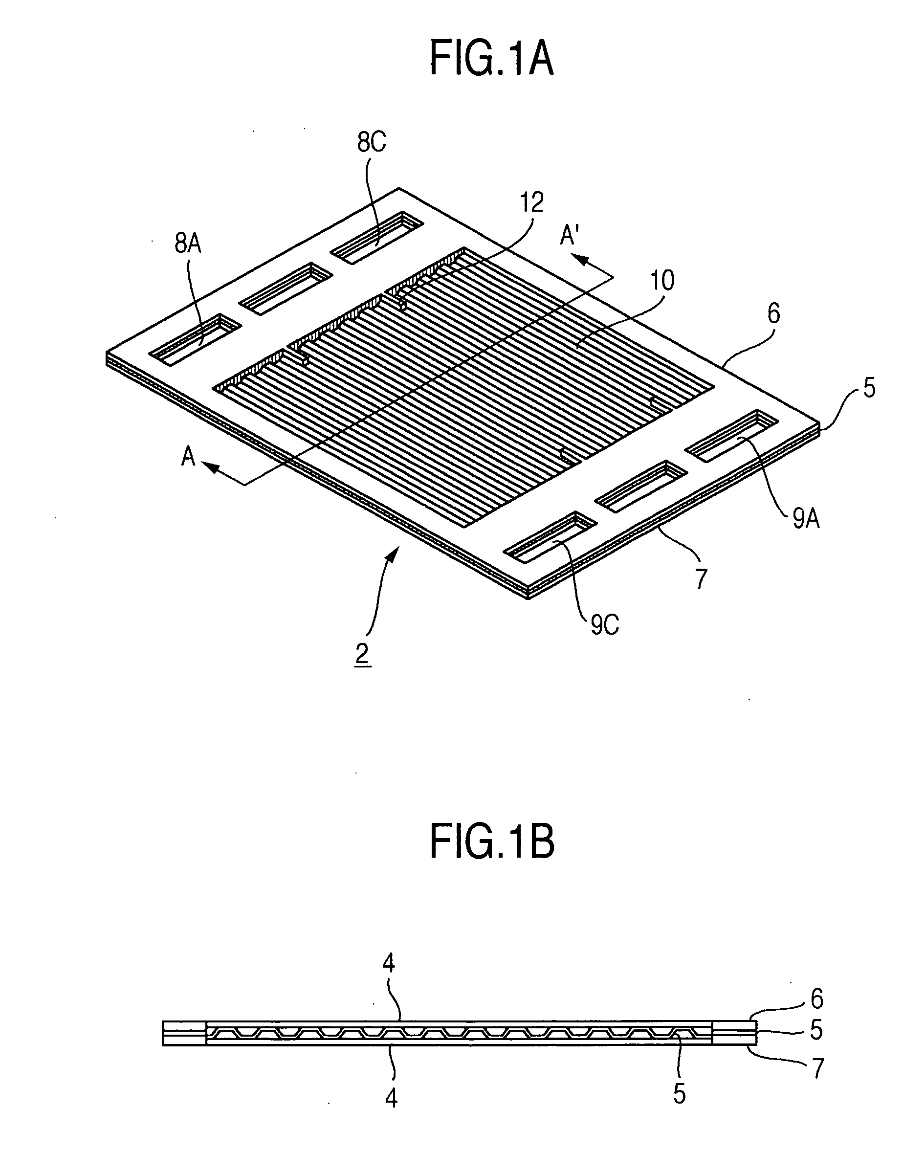
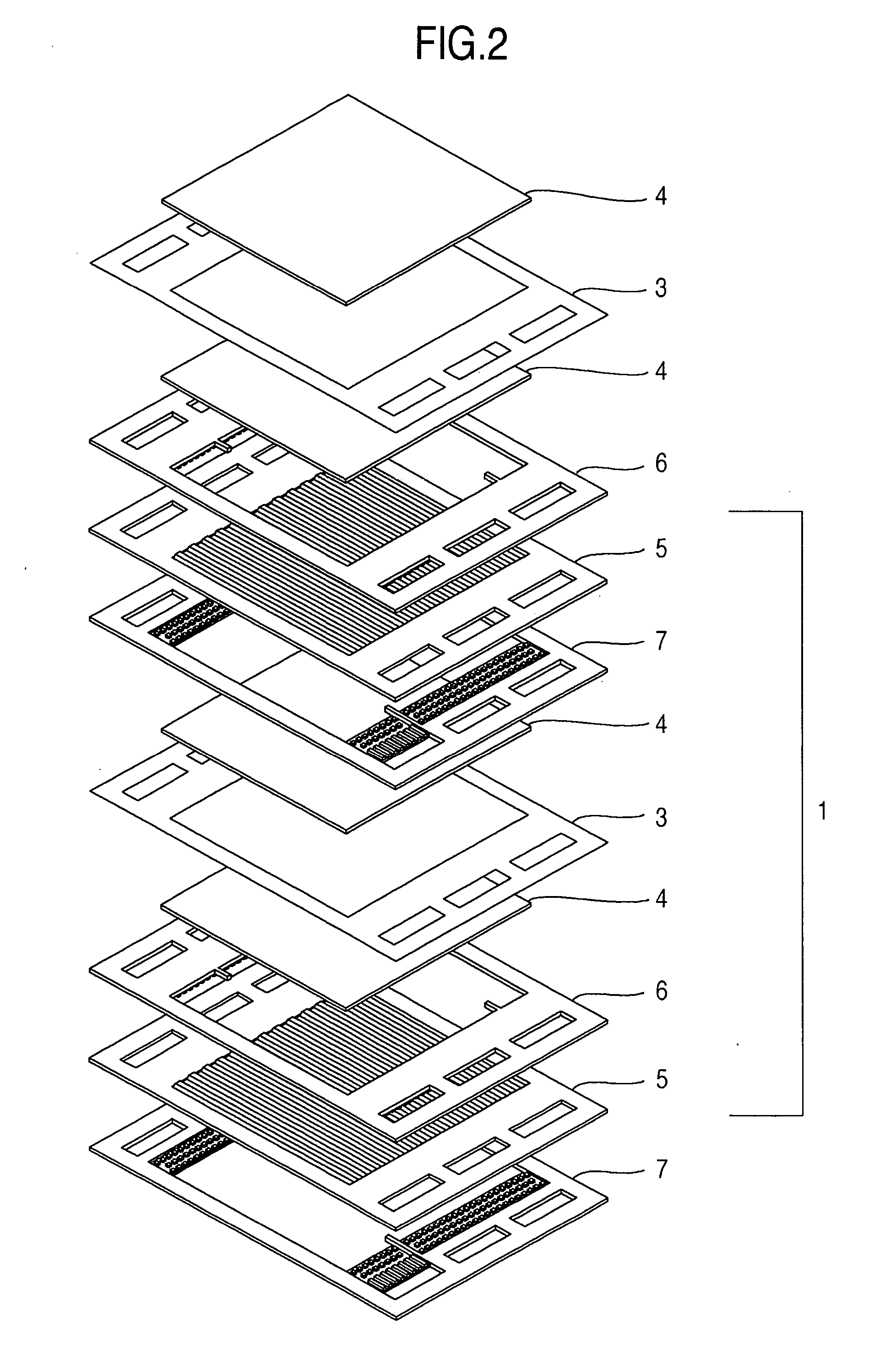
[0055]FIG. 1A is a perspective view showing a structure of a separator unit according to a first embodiment of a fuel cell of the present invention, and FIG. 1B is a sectional view along line A-A′ in FIG. 1A. As is clear in FIGS. 1A and 1B, the separator unit configuring the most important characterizing portion of the embodiments of the present invention has structure in which a separator substrate 5 having multiple parallel flow channel grooves 10 is sandwiched by two frames 6 and 7 (a first frame 6 and a second frame 7). The separator substrate 5 and the frames 6 and 7 have a common fuel gas inlet manifold 8A, a common oxidizer inlet manifold 8C, a common fuel gas outlet manifold 9A and a common oxidizer outlet manifold 9C, and are layered. The first frame 6 has a projection 12 provided thereon so that the cross-sectional area of the flow channels in the downstream portion becomes smaller than that in the upstream portion, that is, the number of the flow channel grooves in the do...

embodiment 2

[0068]FIG. 10 shows the structure of a cooling unit according to an embodiment of the fuel cell of the present invention. The flow channel grooves 10 provided on the separator substrate 5 shown in the first embodiment, and cooling unit flow channel guide portions 18A, 18B provided on a cooling unit frame 17 are incorporated to form the cooling unit flow channel. The coolant is supplied from an inlet manifold 19 of the cooling unit, is led to the flow channel grooves 10 on the separator substrate by the inlet side cooling unit flow channel guide portion 18A, and is reversed in flow direction by means of the outlet side cooling unit flow channel guide portion 18B so as to move back on the flow channel grooves of the separator substrate. Further, the flow direction is reversed by the inlet side cooling unit flow channel guide portion 18A, and it goes along the outlet side cooling unit flow channel guide portion 18B from the flow channel grooves 10 on the separator substrate to be disch...


PUM


Abstract

A fuel cell includes multiple generating units layered in multiple, each unit including an electrolyte membrane electrode assembly, gas diffusion layers placed to sandwich the assembly, and a pair of separator units placed outside the gas diffusion layers, wherein a flow channel space is formed between the separator units and the gas diffusion layers, each of the separator units has a separator substrate with multiple gas flow channel grooves, and a pair of frames placed on both surfaces of the substrate, and the cross-sectional area of the flow channel in a direction orthogonal to the direction of the flow channel grooves is different in an upstream portion and a downstream portion. The present invention also discloses a fuel cell separator unit kit and a fuel cell generating unit kit.

Description

BACKGROUND OF THE INVENTION [0001] 1. Field of the Invention [0002] The present invention relates to a fuel cell, a separator unit kit for a fuel cell and a fuel cell generating unit kit, and in particular to flow channel structure of a fuel cell separator unit. [0003] 2. Description of the Prior Art [0004] In a polymer electrolyte fuel cell, an electrolyte membrane electrode assembly (hereafter referred to as a membrane electrode assembly) in which both sides of a polymer electrolyte membrane are coated with electrode catalysts consisting of an anode and a cathode is inserted between gas diffusion layers and further, separators for supplying a fuel gas and an oxidizer gas are placed on both sides of the membrane electrode assembly to constitute a unit cell (a generating unit). A layered body is formed by placing the plurality of unit cells, and both ends of the layered body are fastened with fastening plates so as to constitute a fuel cell stack. This fuel cell stack is laminated a...

Claims


Application Information

Patent Timeline
IPC IPC(8): H01M8/02H01M4/94H01M8/04H01M8/10H01M8/24
CPCH01M8/0265Y02E60/50H01M8/04007H01M8/0273
Inventor TAKAHASHI, KOYAMAUCHI, HIROSHIYAMAGA, KENJI
Owner HITACHI LTD
Why Eureka
Try Eureka