Connector assembly

Active Publication Date: 2005-11-17
RGB SYST INC
View PDF2 Cites 7 Cited by
  • Summary
  • Abstract
  • Description
  • Claims
  • Application Information

AI Technical Summary

Benefits of technology

[0010] A connector assembly for one or more electronics connectors, such as input/output jacks or ports, and a method of utilizing a connector assembly are described. Embodiments of the conne

Problems solved by technology

When multiple BNC connectors are installed on a printed circuit board, the integrity of the PCB board may be compromised each time a cable plug is attached to or removed from one of the connectors.
The printed circuit board is flexible whereas the connectors are generally inflexible, resulting in the creation of stress points where the connectors meet the PC board.
The frequent attachment and removal of cable plugs from the assembly may result in wearing of the PC board material and/or cracking of traces or solder on the printed circuit board, particularly in the vicinity of the connectors.
Thus, after repeated use, these electronic devices may fail.
Another issue with placing multiple connectors on a PC board is that each connector must be individually placed and sol

Method used


Image

  • Connector assembly
  • Connector assembly
  • Connector assembly

Examples


Embodiment Construction

[0022] A connector assembly for one or more electronics connectors and a method of utilizing the connector assembly are described. In the following description, numerous specific details are set forth in order to provide a more thorough description of the present invention. It will be apparent, however, to one skilled in the art, that the present invention may be practiced without these specific details. In other instances, well-known features have not been described in detail so as not to obscure the invention.

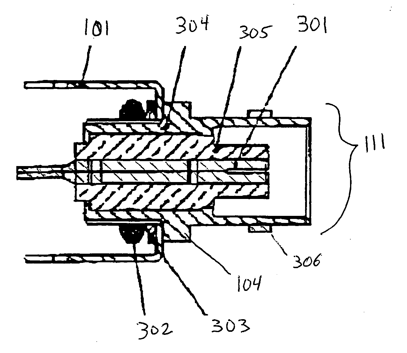
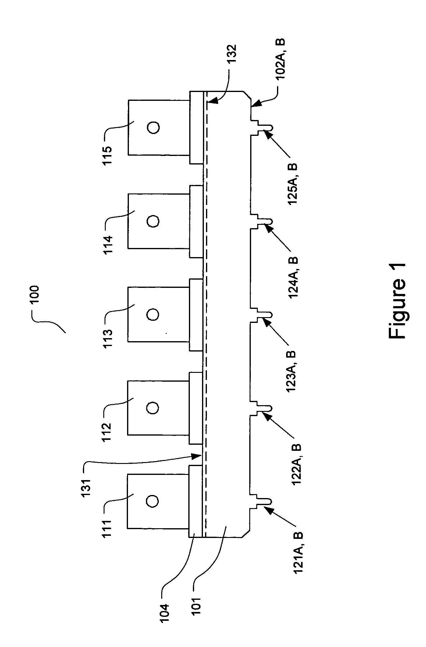
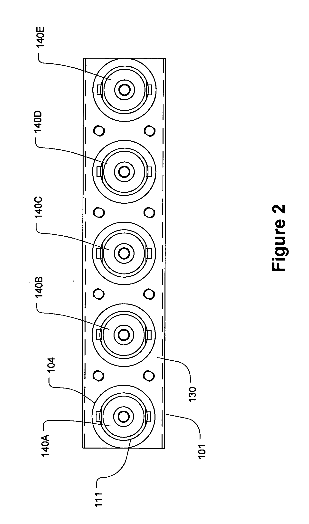
[0023] In general, one or more embodiments of the invention may include an assembly for a plurality of connectors (e.g., audio / video) to be mounted, as a group, on a printed circuit board (PCB or PC board). The connector assembly of the present invention may be configured for a plurality of input / output connectors. For instance, an embodiment of the present invention may include a plurality of BNC connectors for audio / video equipment.

[0024] In one embodiment, the connector ...


PUM


Abstract

A connector assembly and a method of utilizing a connector assembly to enhance performance, improve reliability and provide ease of assembly of electronic equipment are presented. The connector assembly comprises a rigid bracket capable of holding multiple connectors. The bracket acts as a common ground for all of the connectors. The connector assembly has multiple legs and connector conductors that insert into corresponding apertures on a PCB. The legs of the connector assembly are configured to permit the placement of circuit traces on the PCB in the spaces between the legs. After placement of the connector assembly onto the PCB, soldering or other techniques may be used to secure the connector assembly to the board and to connect the proper circuits to the connectors. Because the connectors are installed on the rigid bracket, repeated physical stresses induced on the ports or jacks do not affect the integrity of the PCB.

Description

BACKGROUND OF THE INVENTION [0001] 1. Field of the Invention [0002] The present invention relates to electronic communication equipment, and more particularly to a connector assembly for electronic hardware. [0003] 2. Background Art [0004] There are a wide variety of instances in which it is desirable to mount connectors, such as input / output ports (or jacks) on a printed circuit board, for transmission of signals between different internal elements of an electronic device or for transmission of signals between one or more elements of the device and electronic equipment external to the device. For example, audio / video devices such as switchers may include a number of ports protruding through an outer frame for connecting with a number of external electronic devices. Each port is typically connected, within the switcher or other type of device, to one or more unshielded wires leading to one or more locations on an internal printed circuit board (PCB or PC board) that deliver an outpu...

Claims


Application Information

Patent Timeline
IPC IPC(8): H01R12/00H01R13/646H01R13/74
CPCH01R13/746H01R2103/00H01R24/50
Inventor GEIL, JACOBKEUNG, WILLIAM
Owner RGB SYST INC
Why Eureka
Try Eureka