
Transaction-based storage system and method that uses variable sized objects to store data

a storage system and variable-sized object technology, applied in the field of storage technology, can solve the problems of limited latency of a given single operation, small practical limit to the number of disks, and very fast sequential operations, and achieve the effect of little performan

Active Publication Date: 2005-11-17
COUSINS ROBERT E
View PDF7 Cites 136 Cited by
  • Summary
  • Abstract
  • Description
  • Claims
  • Application Information

AI Technical Summary

Benefits of technology

"The present invention provides a storage system for storing variable sized objects using arrays of disks. The system uses a rank manager to dynamically configure the ranks to adjust for failed and added disks by selectively shortening and lengthening the stripes. The system includes a file system that uses variable sized objects and a stripe space table to describe the amount of space used in each stripe. The system also includes an object map to describe the location of each object and a volume index to translate regions of logical storage into object identifiers. The technical effects of the invention include improved performance and flexibility in storing large amounts of data efficiently."

Problems solved by technology

However, the latency of a given single operation will be limited by the underlying performance of the disk drive(s) which service the request.
In fact, sequential operations can be very fast and there is little practical limit to the number of disks which can be used in a RAID 0 configuration.
One disadvantage of RAID 0 is that if any single disk fails, the entire array fails.
However, as the array becomes larger, the reliability goes down so there is a natural limit to the viable maximum size for a RAID 0 configuration.
Sequential reads are really no faster than a single disk.
(However, write operations are usually slightly slower than on single disk configurations since two writes must complete instead of only one.)
Some disadvantages of RAID 1 are: Space Inefficient—If two disks are in a RAID 1, then the usable space is equal to the capacity of only one disk.
RAID 4 is not particularly popular because of some disadvantages and the fact that relatively little software can take advantage of its advantages.
However, the parity disk contains redundant information—information which is “extra” and allows the contents of one of the other drives to be deduced in case of failure.
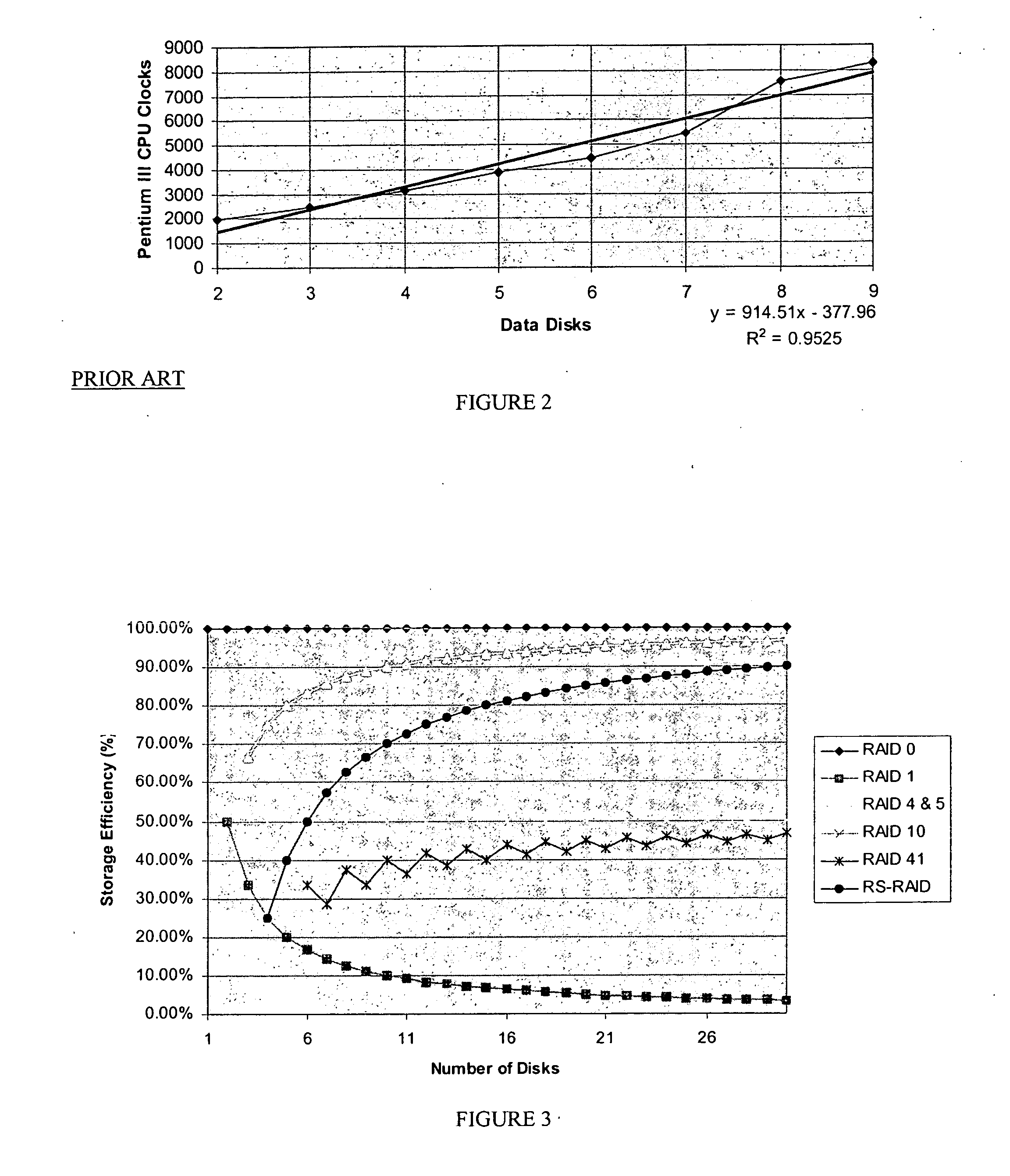
However, modern 64-bit CPUs can typically perform the calculation on 64 bits at a time reducing the effort to perform the parity calculations dramatically. FIG. 2 is a chart showing representative CPU clock counts for parity calculations for various widths of RAID 4 implementations using a Pentium III (and not well optimized code).
The parity calculations require some CPU time, but are much faster than the disk transaction.
Furthermore, two randomly distributed writes will not benefit from the parallelism in the array because the writes must queue for the shared parity disk.
The parallelism of the array will help to reduce the length of a given disk's queue, but not its ability to drain the queue.
Some disadvantages of RAID 4 include: Slow Writes—The RAID write bottleneck is a huge problem for most environments.
RAID 4 has not been particularly popular due to its comparative disadvantages (in most situations) to RAID 5.
The fact that RAID 4 must store and retrieve the parity information from a dedicated disk generates the write bottleneck.
One disadvantage of this approach is that the subsystem must now perform a much more complex mapping operation when converting from logical to physical addresses.
However, in modem multitasking environments there are often a number of requests in the queue so the subsystem can usually keep every disk busy—albeit at a somewhat lower transaction rate.)
However, RAID 10 cannot survive the loss of any 2 disks so it is actually not much more reliable than RAID 4 or RAID 5.
Some drawbacks to RAID 41 are: it requires lots of disks (minimum 6), and low space utilization.
More disks increase the price of rebuilding when a disk fails and increases the likelihood of a failure—making RAID 5 an unscalable solution.
However, today, this is a more arbitrary constraint since volumes often have little to do with the size of the underlying disk(s).)
In other words, it may be possible to read 200 consecutive sectors starting at location x in one request, but it is not possible to read every 10th sector in the first 2000 sectors in one request.
Their file services were necessarily limited and the file system designs placed simplicity and reliability at a premium.
Furthermore, early disk drives were typically only a handful of megabytes so scalability was often unimportant.
Almost no file system uses blocks smaller than a sector due to the complexity of blocking / deblocking contents into sectors.
Traditional block oriented file systems such as FFS have proven to have reasonable throughput and stability, but they are not “perfect.” Over time, the limitations of FFS (and its ilk) have become more and more problematic.
Specifically, during times of peak write activity, FFS wastes a lot of time seeking and performing relatively small (8K) transfers.
Furthermore the fsck problem (described below) can be problematic when fast crash recovery is important such as with online services or financial services.
(Shared servers today can serve hundreds of users so a 15-minute fsck can result in dozens or even hundreds of lost worker hours.)
File system use tends to be bursty.
If the write load becomes too heavy, the journal grows faster than it can be retired.

Method used


Image

  • Transaction-based storage system and method that uses variable sized objects to store data
  • Transaction-based storage system and method that uses variable sized objects to store data
  • Transaction-based storage system and method that uses variable sized objects to store data

Examples


Embodiment Construction

[0132] The present invention will now be described in detail with reference to the drawings, which are provided as illustrative examples of the invention so as to enable those skilled in the art to practice the invention. Notably, the implementation of certain elements of the present invention can be accomplished using software, hardware, firmware or any combination thereof, as would be apparent to those of ordinary skill in the art, and the figures and examples below are not meant to limit the scope of the present invention. Moreover, where certain elements of the present invention can be partially or fully implemented using known components, only those portions of such known components that are necessary for an understanding of the present invention will be described, and detailed descriptions of other portions of such known components will be omitted so as not to obscure the invention. Preferred embodiments of the present invention are illustrated in the Figures, like numerals be...


PUM


Abstract

The present invention provides a storage system for storing variable sized objects. The storage system is preferably a transaction-based system that uses variable sized objects to store data. The storage system is preferably implemented using arrays disks that are arranged in ranks. Each rank includes multiple stripes. Each stripe may be read and written as a convenient unit for maximum performance. A rank manager is able to dynamically configure the ranks to adjust for failed and added disks by selectively shortening and lengthening the stripes. The storage system may include a stripe space table that contains entries describing the amount of space used in each stripe. An object map provides entries for each object in the storage system describing the location (e.g., rank, stripe and offset values), the length and version of the object. A volume index translates regions of logical storage into object identifiers. The storage system may implement various types of formats such as I-node, binary tree and extendible hashing formats.

Description

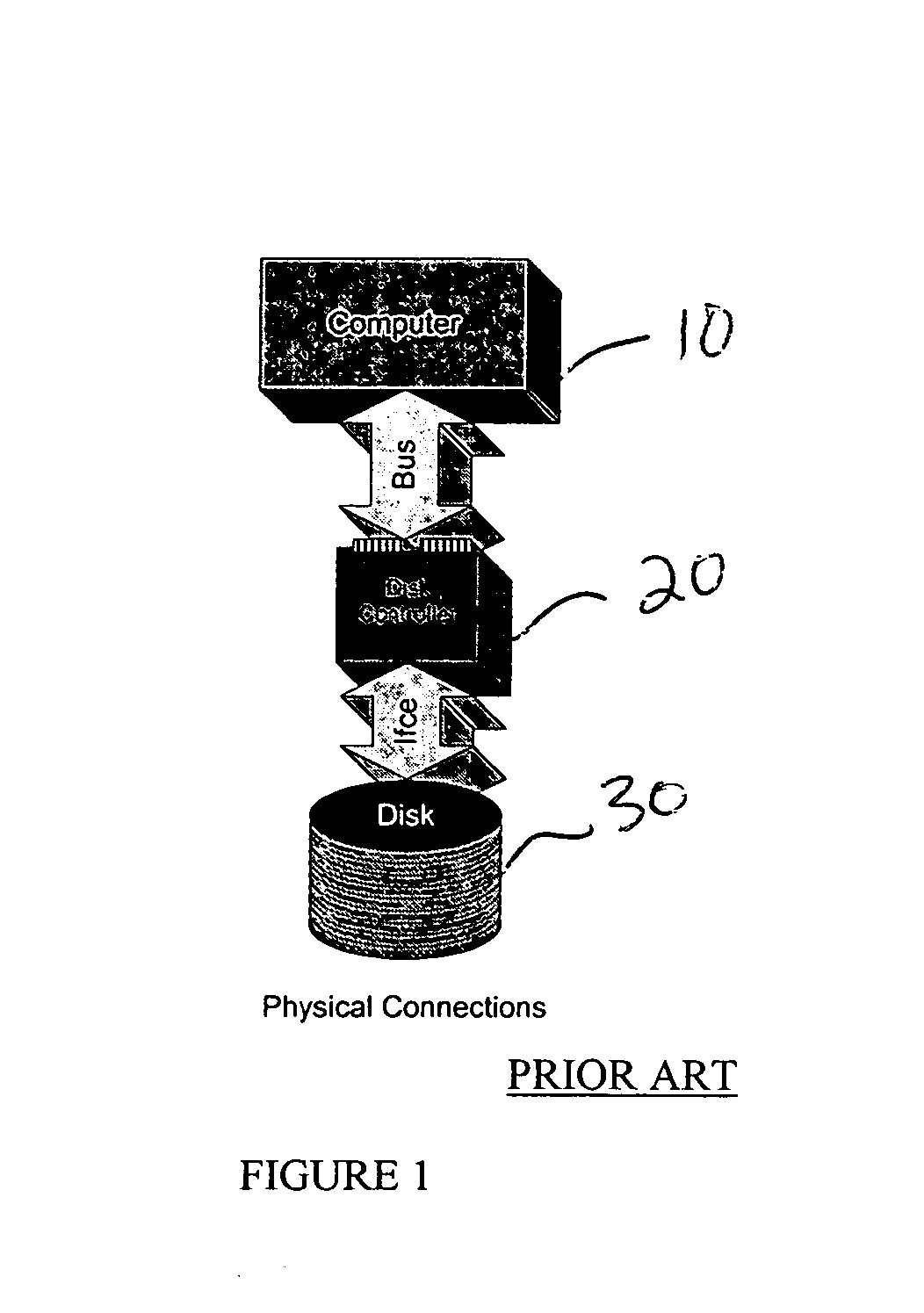
FIELD OF THE INVENTION [0001] The present invention generally relates to storage technology and more particularly to a transaction-based storage system and method for managing file and block data, which uses variable sized objects to store data. BACKGROUND OF THE INVENTION [0002] Historically, computer storage has followed an approach as shown generally in FIG. 1. Physically, a computer 10 contains a disk controller 20—a piece of hardware which provides an electrical connection to a disk. Normally, the disk controller 20 is a chip or card in the system. The controller is electrically connected to one or more disk drives 30 which are used to store and retrieve data. I. Redundant Arrays of Independent Disks (RAID) [0003] RAID (redundant array of independent disks) is a way of storing the same data in different places (thus, redundantly) on multiple disks. By placing data on multiple disks, I / O operations can overlap in a balanced way, improving performance. Since multiple disks incre...

Claims


Application Information

Patent Timeline
Patent Type & Authority Applications(United States)
IPC IPC(8): G06F12/16
CPCG06F2211/1026G06F17/30067G06F16/10G06F16/13G06F11/2069G06F3/0619G06F3/064G06F3/0689G06F3/0641G06F3/065G06F11/1092G06F11/2058
Inventor COUSINS, ROBERT E.
Owner COUSINS ROBERT E
Learn More