Ballistic injection nrom flash memory

a flash memory and ballistic injection technology, applied in the field of memory devices, can solve the problems of affecting the operation of flash memory cells

Active Publication Date: 2005-11-24
MICRON TECH INC
View PDF16 Cites 57 Cited by
  • Summary
  • Abstract
  • Description
  • Claims
  • Application Information

AI Technical Summary

Problems solved by technology

However, a problem with decreased flash memory size is that flash memory cell technologies have some scaling limitations due to the high voltage requirements for program and erase operations.
As MOSFETs are scaled to deep sub-micron dimensions, it becomes more difficult to maintain an acceptable aspect ratio.
However, it is extremely difficult to scale the junction depths to 100 nm-200 nm (1000 Å to 2000 Å) since these are doped by ion implantation and diffusion.
Another problem with flash memories is program speed.

Method used


Image

  • Ballistic injection nrom flash memory
  • Ballistic injection nrom flash memory
  • Ballistic injection nrom flash memory

Examples


Embodiment Construction

[0022] In the following detailed description of the invention, reference is made to the accompanying drawings that form a part hereof and in which is shown, by way of illustration, specific embodiments in which the invention may be practiced. In the drawings, like numerals describe substantially similar components throughout the several views. These embodiments are described in sufficient detail to enable those skilled in the art to practice the invention. Other embodiments may be utilized and structural, logical, and electrical changes may be made without departing from the scope of the present invention. The following detailed description is, therefore, not to be taken in a limiting sense, and the scope of the present invention is defined only by the appended claims and equivalents thereof.

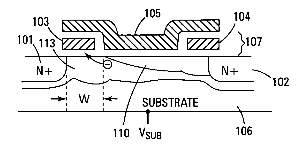
[0023]FIG. 1 illustrates a cross-sectional view of one embodiment of a planar split nitride layer NROM flash memory cell of the present invention. The cell is comprised of a substrate 106 that ...


PUM


Abstract

A split NROM flash memory cell is comprised of source / drain regions in a substrate. The split nitride charge storage regions are insulated from the substrate by a first layer of oxide material and from a control gate by a second layer of oxide material. The nitride storage regions are isolated from each other by a depression in the control gate. In a vertical embodiment, the split nitride storage regions are separated by an oxide pillar. The cell is programmed by creating a positive charge on the nitride storage regions and biasing the drain region while grounding the source region. This creates a virtual source / drain region near the drain region such that the hot electrons are accelerated in the narrow pinched off region. The electrons become ballistic and are directly injected onto the nitride storage region that is adjacent to the pinched off channel region.

Description

TECHNICAL FIELD OF THE INVENTION [0001] The present invention relates generally to memory devices and in particular the present invention relates to nitride read only memory cells. BACKGROUND OF THE INVENTION [0002] Memory devices are typically provided as internal, semiconductor, integrated circuits in computers or other electronic devices. There are many different types of memory including random-access memory (RAM), read only memory (ROM), dynamic random access memory (DRAM), synchronous dynamic random access memory (SDRAM), and flash memory. One type of flash memory is a nitride read only memory (NROM). NROM has some of the characteristics of flash memory but does not require the special fabrication processes of flash memory. NROM integrated circuits can be implemented using a standard CMOS process. [0003] Flash memory devices have developed into a popular source of non-volatile memory for a wide range of electronic applications. Flash memory devices typically use a one-transist...

Claims


Application Information

Patent Timeline
Patent Type & Authority Applications(United States)
IPC IPC(8): G11C11/34G11C16/04G11C16/10G11C16/26H01L21/28H01L29/00H01L29/423H01L29/792
CPCG11C16/0466G11C16/10G11C16/26H01L29/7923H01L29/42348H01L29/42352H01L21/28282H01L29/40117
Inventor FORBES, LEONARD
Owner MICRON TECH INC
Why Eureka
Try Eureka