

Information reproduction apparatus and information reproduction method
- Summary
- Abstract
- Description
- Claims
- Application Information
AI Technical Summary
Benefits of technology
Problems solved by technology
Method used
Image

Examples
first embodiment
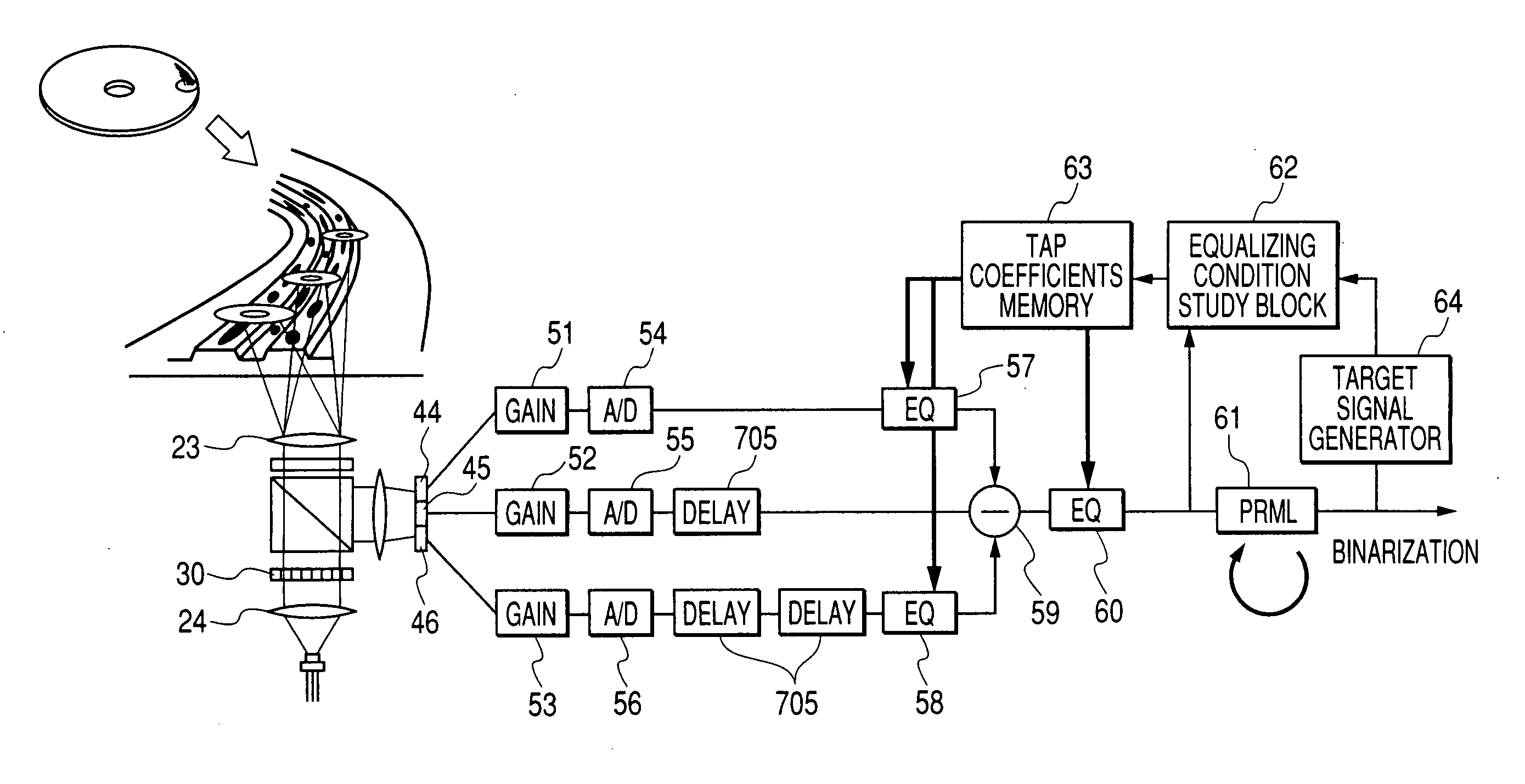
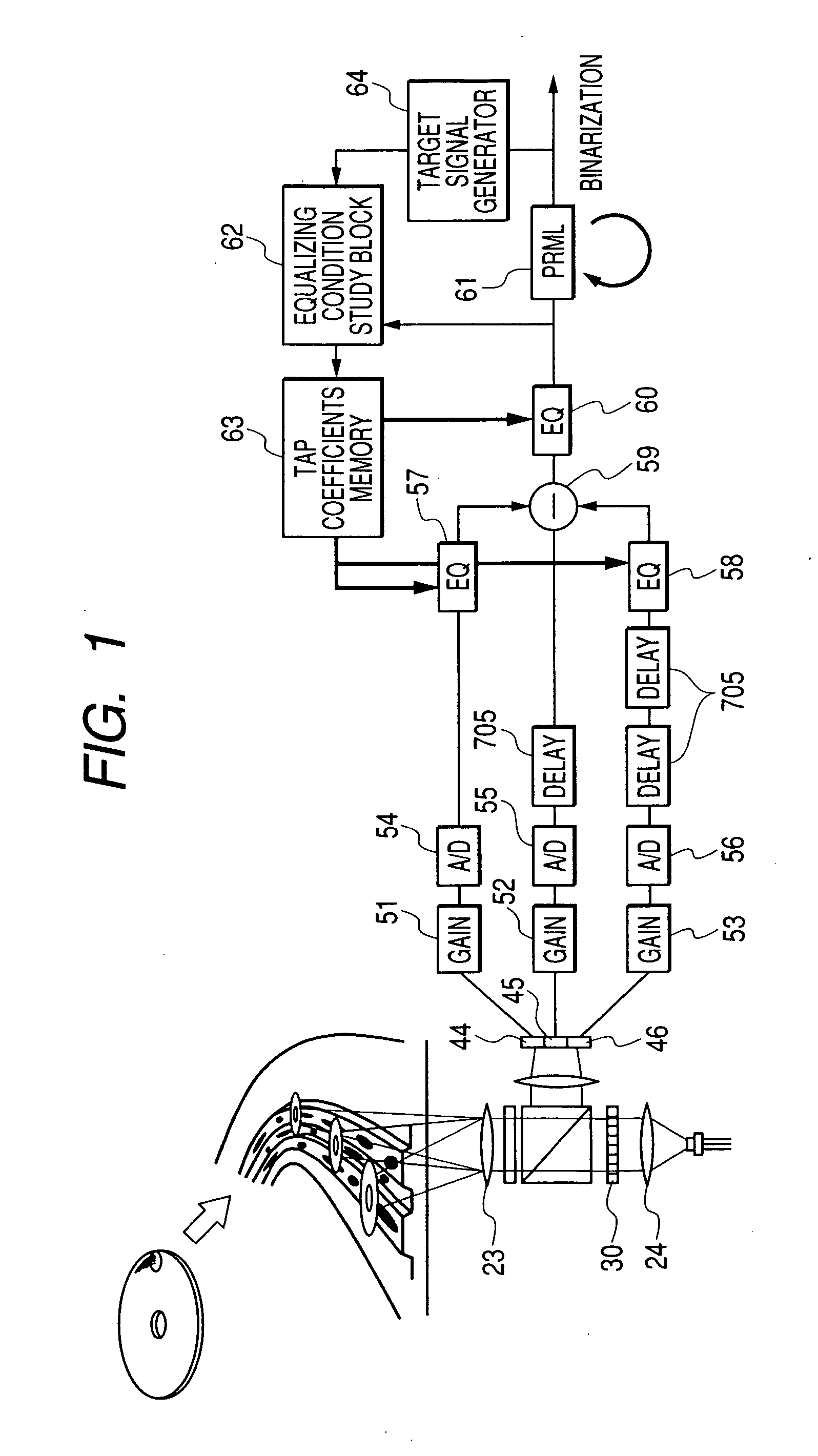
[0057]FIG. 1 shows a block diagram of an information recording apparatus in an embodiment of the present invention for realizing cross-talk cancellation at high track density.
[0058] A laser beam emitted from a laser beam source is passed through a collimating lens 24 to obtain a collimated beam, which is then divided into three spots by a diffraction grating 30. The divided three beam spots are positioned in three tracks (front, center, and rear) at almost an equal distance (7 μm) from each another by the diffraction grating so that they are protected from mutual interference. The center spot is assumed as the main spot and two spots at both sides of the center spot are assumed as side spots. The laser beam is focused so that the center spot is formed in the target track.
[0059] In the verification of the present invention, the laser beam is set at a wavelength of 405 nm and at a numerical aperture of 0.85. Consequently, the beam spot diameter becomes 410 nm that is calculated from...
second embodiment
[0078]FIG. 12 shows a block diagram of an information reproduction apparatus in the second embodiment of the present invention. The apparatus can cancel a cross-talk under high density conditions and obtain a cross-talk index simultaneously. The laser beam emitted from a laser beam source is passed through a collimating lens 24 to obtain a collimated beam. The collimated beam is then divided into three beam spots by a diffraction grating 30. The divided three beams are focused by an objective lens 23 on an information recording medium. Then, a polarizing beam splitter and a λ / 4 plate are used to inject the reflected beams from the medium entirely into photo detectors 44 to 46 without returning them to the laser beam source. After that, according to the reproduced signals from the beam spots, which are outputs of the photo detectors 44 to 46, each of the light intensity correcting fixed value circuits 700 and 701 corrects the light intensity of each of the beam spots formed at both s...
third embodiment
[0093]FIG. 15 shows a block diagram of an information reproduction apparatus in the third embodiment of the present invention. In this third embodiment, a switch 709 is provided beyond each of the equalizers 57 and 58 in the first embodiment. In this third embodiment, a decision circuit 710 decides, for example, whether or not information is recorded in object side tracks and the switch 709 provided in a switch controller 708 is turned on / off according to the decision result. If no information is recorded in the side tracks, the switch 709 is turned off to stabilize the processing. The switch 709 is also turned off when in retrying reproduction / studying recording conditions to reduce the reproduction error rate and improve the compatibility of recorded information, thereby stabilizing the processing.
PUM
 Abstract
Description
Claims
Application Information