
Method and reference circuit for bias current switching for implementing an integrated temperature sensor

a technology of bias current switching and temperature sensor, applied in the field of on-chip temperature sensing, can solve the problems of adding appreciably to the cost of typical consumer electronic products, and achieve the effect of minimizing the error in the temperature calculation

Inactive Publication Date: 2005-11-24
IBM CORP
View PDF26 Cites 16 Cited by
  • Summary
  • Abstract
  • Description
  • Claims
  • Application Information

AI Technical Summary

Benefits of technology

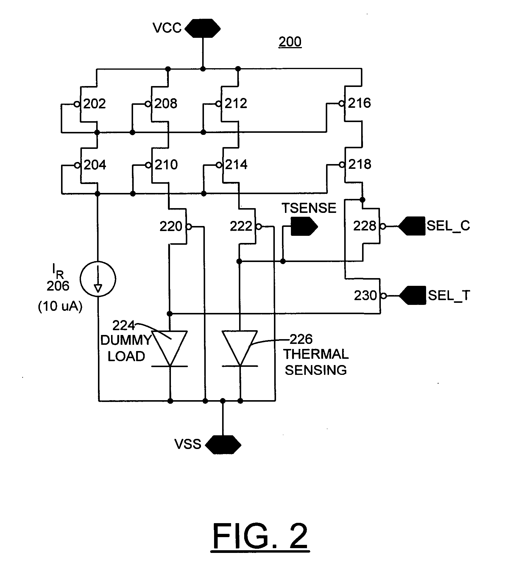
The present invention provides a method and a reference circuit for bias current switching for implementing an integrated temperature sensor. The method and reference circuit minimize error in temperature calculation and overcome many of the disadvantages of prior art arrangements. The reference circuit includes a reference current source and a current multiplier that provides a multiplied current to the thermal sensing diode. The second bias current to the thermal sensing diode includes the first bias current and the multiplied current from the current multiplier. The second bias current is provided by selectively switching the multiplied current between the thermal sensing diode and a dummy load diode. The reference circuit is formed on chip with an integrated circuit receiving an output signal of the integrated temperature sensor. The technical effects of the present invention are to minimize error in temperature calculation and provide a more accurate integrated temperature sensor.

Problems solved by technology

Such separate temperature sensor modules add appreciably to the cost of typical consumer electronic products that use microprocessor or other logic that require a temperature monitoring function.

Method used


Image

  • Method and reference circuit for bias current switching for implementing an integrated temperature sensor
  • Method and reference circuit for bias current switching for implementing an integrated temperature sensor
  • Method and reference circuit for bias current switching for implementing an integrated temperature sensor

Examples


Embodiment Construction

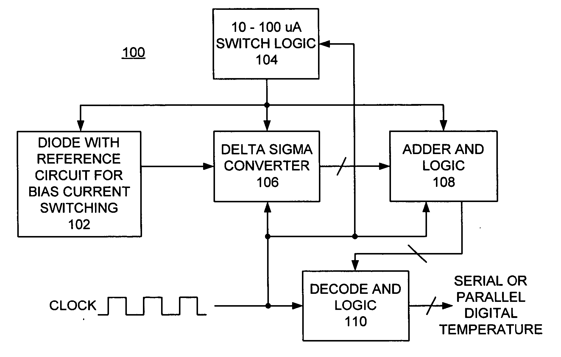
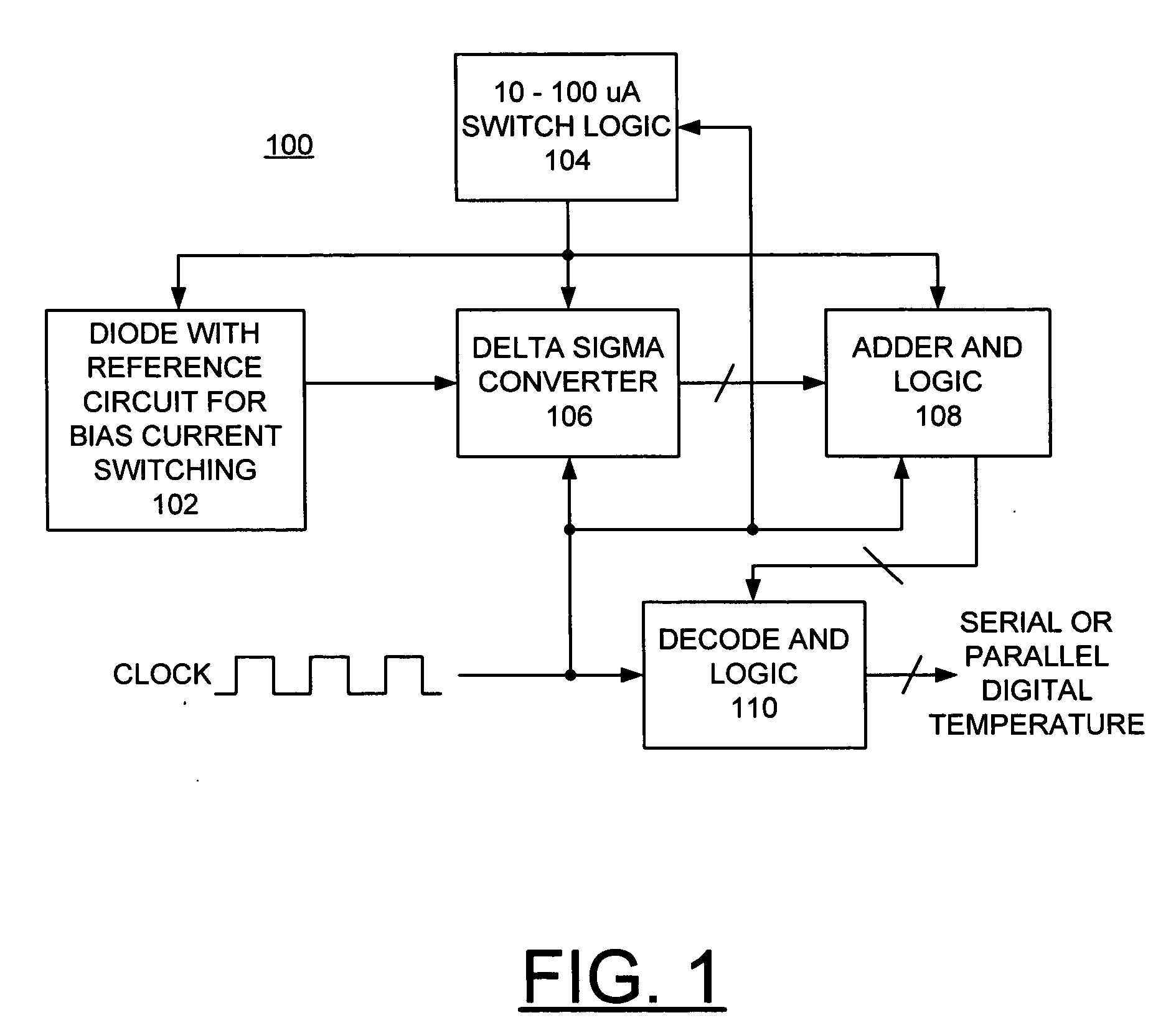
[0011] Having reference now to the drawings, in FIG. 1, there is shown an integrated temperature sensor generally designated by the reference character 100 in accordance with the preferred embodiment. The integrated temperature sensor 100 includes a diode with a reference circuit for bias current switching block 102 of the preferred embodiment. The diode at block 102 is a thermal sensing diode used to measure temperature. An exemplary reference circuit of the preferred embodiment for the integrated temperature sensor 100 is illustrated and described with respect to FIG. 2. A switch logic block 104 provides a control signal to the diode with a reference circuit for bias current switching block 102 to switch between a first diode bias current and a second diode bias current, such as between 10 μA and 100 μA. A delta sigma converter 106 coupled to a thermal sensing diode at block 102 calculates a voltage difference of the diode at the first and second diode bias currents. The diode vol...


PUM

PropertyMeasurementUnit
bias currentaaaaaaaaaa
currentaaaaaaaaaa

Abstract

A method and a reference circuit for bias current switching are provided for implementing an integrated temperature sensor. A first bias current is generated and constantly applied to a thermal sensing diode. A second bias current is provided to the thermal sensing diode by selectively switching a multiplied current from a current multiplier to the thermal sensing diode or to a load diode. The reference circuit includes a reference current source coupled to current mirror. The current mirror provides a first bias current to a thermal sensing diode. The current mirror is coupled to a current multiplier that provides a multiplied current. A second bias current to the thermal sensing diode includes the first bias current and the multiplied current from the current multiplier. The second bias current to the thermal sensing diode is provided by selectively switching the multiplied current between the thermal sensing diode and a dummy load diode.

Description

FIELD OF THE INVENTION [0001] The present invention relates generally to an on-chip temperature sensing, and more particularly, relates to a method and a reference circuit for bias current switching for implementing an integrated temperature sensor. DESCRIPTION OF THE RELATED ART [0002] Various arrangements are known for implementing temperature sensing using a temperature sensor to generate a signal that indicates chip temperature. Temperature sensors often are implemented by a discrete module formed by a precision analog bipolar or bipolar complementary-metal-oxide-semiconductor (BICMOS) circuit design. Such separate temperature sensor modules add appreciably to the cost of typical consumer electronic products that use microprocessor or other logic that require a temperature monitoring function. [0003] A need exists for an integrated temperature sensor that is effective and reliable, and that is generally cost effective. SUMMARY OF THE INVENTION [0004] Principal aspects of the pre...

Claims


Application Information

Patent Timeline
Patent Type & Authority Applications(United States)
IPC IPC(8): G01K7/00G01K7/01
CPCG01K7/01
Inventor PHAN, NGHIA VANROSNO, PATRICK LEESTROM, JAMES DAVID
Owner IBM CORP
Learn More