
Frequency domain equalization of communication signals

a technology of communication signals and frequency domains, applied in the field of digital telecommunication, can solve problems such as noise in the signal, multi-path distortion of the transmitted signal, typical distortion of the tv channel, etc., and achieve the effect of greater time separation

Active Publication Date: 2005-11-24
COHERENT LOGIX
View PDF8 Cites 34 Cited by
  • Summary
  • Abstract
  • Description
  • Claims
  • Application Information

AI Technical Summary

Benefits of technology

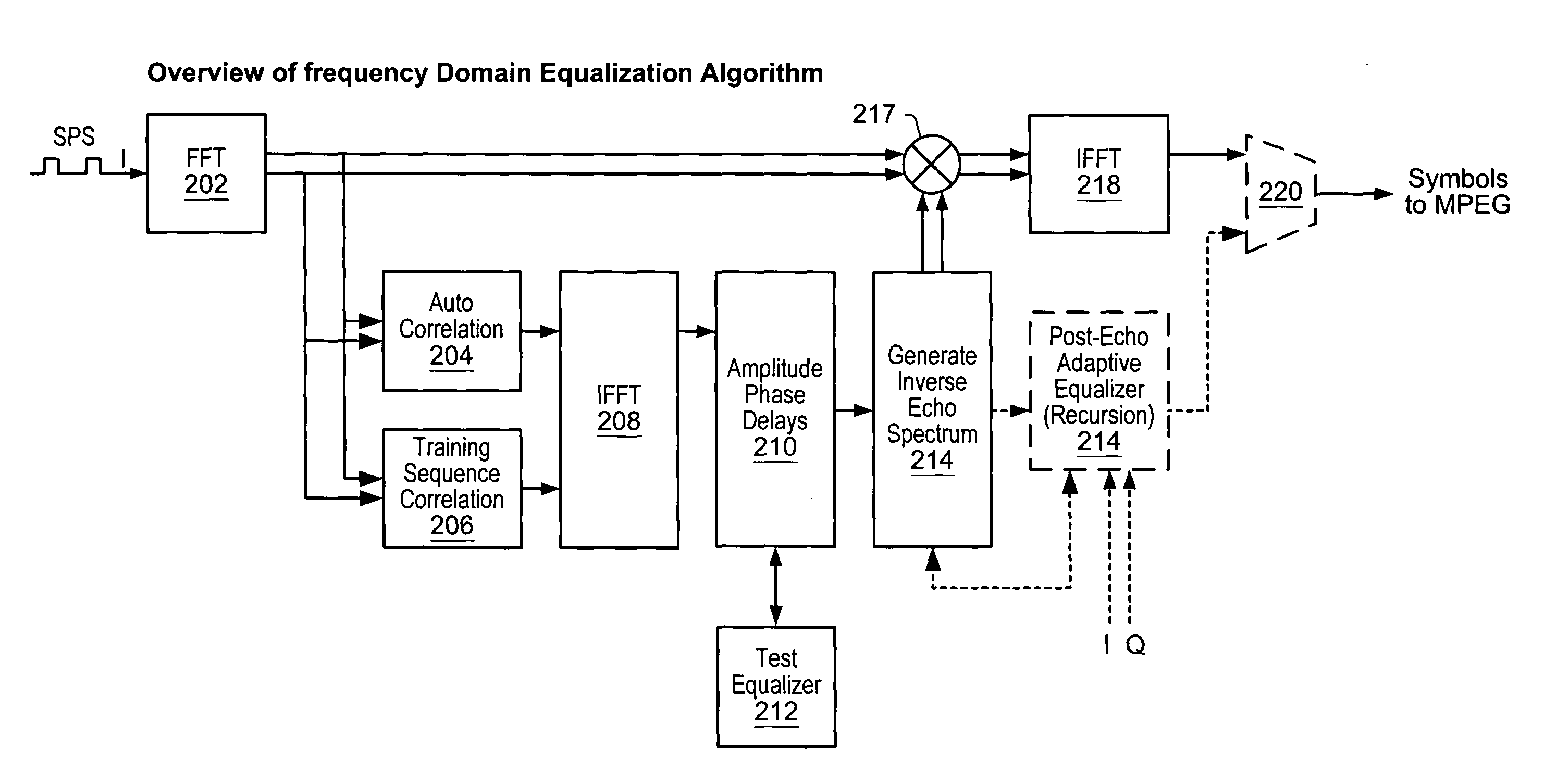
[0033] Various embodiments of the present invention are directed to an equalization method. In one set of embodiments, the invention comprises a frequency domain equalization algorithm (FDEA). The FDEA is based on transforming the inbound symbol stream to the frequency domain, multiplying the real-time spectrum by a distortion-canceling spectrum, and then transforming the resulting spectrum back to the time domain for output of a symbol stream in the time domain. The frequency domain equalization algorithm may achieve a number of advantages over conventional digital filters. Such advantages may include the ability to compensate for echoes with greater time separation from the main path, the ability to compensate for pre-echoes as well as post-echoes, the ability to compensate for much more severe Doppler shifts, rapid convergence, and continuous updating.

Problems solved by technology

The reflections and diffraction from these objects can create multi-path distortion of the transmitted signal.
Typical distortions in a TV channel come from reflections from buildings and aircraft.
The channel may also introduce noise into the signal, where the noise may be white or impulsive (bursting).
For digital signals, noise can cause decision circuits to make symbol errors.
However, the more complex the distortions, the more complex the compensation required, ultimately requiring a larger equalizer circuit.
In DSL modem applications, the symbol rate is allowed to vary depending on line quality, however the maximum symbol rate is limited by the receiver's analog sampling rate, currently at about 2.2 M samples per second.
Thus equalizers designed for DSL generally would not work for radio / television, especially for HDTV where the symbol rate is higher, about 10.8 M symbols per sec, and the channel fluctuates sometimes up to tens of Hertz.
One reason is that frequency domain digital equalizers have a higher computational complexity, which in the past would have produced excessive receiver cost.
Because of the feedback, IIR filters can cancel longer delayed echoes better than FIR filters, however, their stability is not assured.
However, this approach to channel equalization has various problems.
However, this process can be rather slow and is definitely not suitable for any multipath signal, such as some airplane flutter, that varies quite quickly with elapsed time.
However, currently the limiting factor on the speed of initially equalizing the reception channel or of tracking a time-varying multipath is established by the processing speeds of the computing devices being utilized.
Testing on dynamic echoes was very limited at the time.
Faster algorithms with low complexity are also an area in need of further research, since the Godard algorithm can be quite slow in tracking rapidly varying channels.
Finally, while the literature on the analyses of blind algorithms for linear equalizers is very rich, the same is not true for blind algorithms for DFE's with significant error propagation.
Slow convergence when using the PN sequence for training, and therefore an inability to track Doppler shifts or other dynamic multipath distortion.
Poor ability to center on the strongest path signal and cancel pre-echoes.
Limited range of echo delays due to steep cost rise to get beyond 200 taps.
Since a multiply is required for each tap, a large number of multipliers are needed for long delays, adding power consumption.
Stability issues when using IIR filters.

Method used


Image

  • Frequency domain equalization of communication signals
  • Frequency domain equalization of communication signals
  • Frequency domain equalization of communication signals

Examples


Embodiment Construction

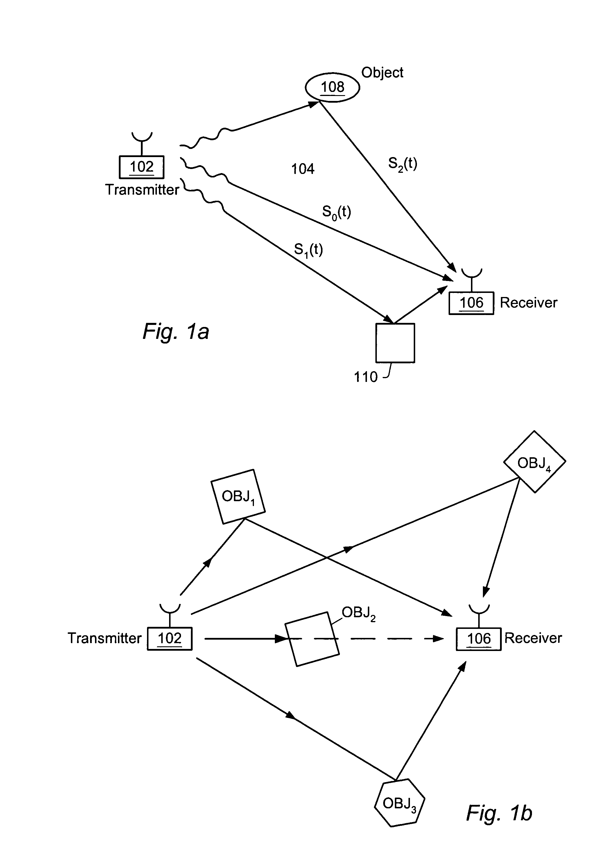
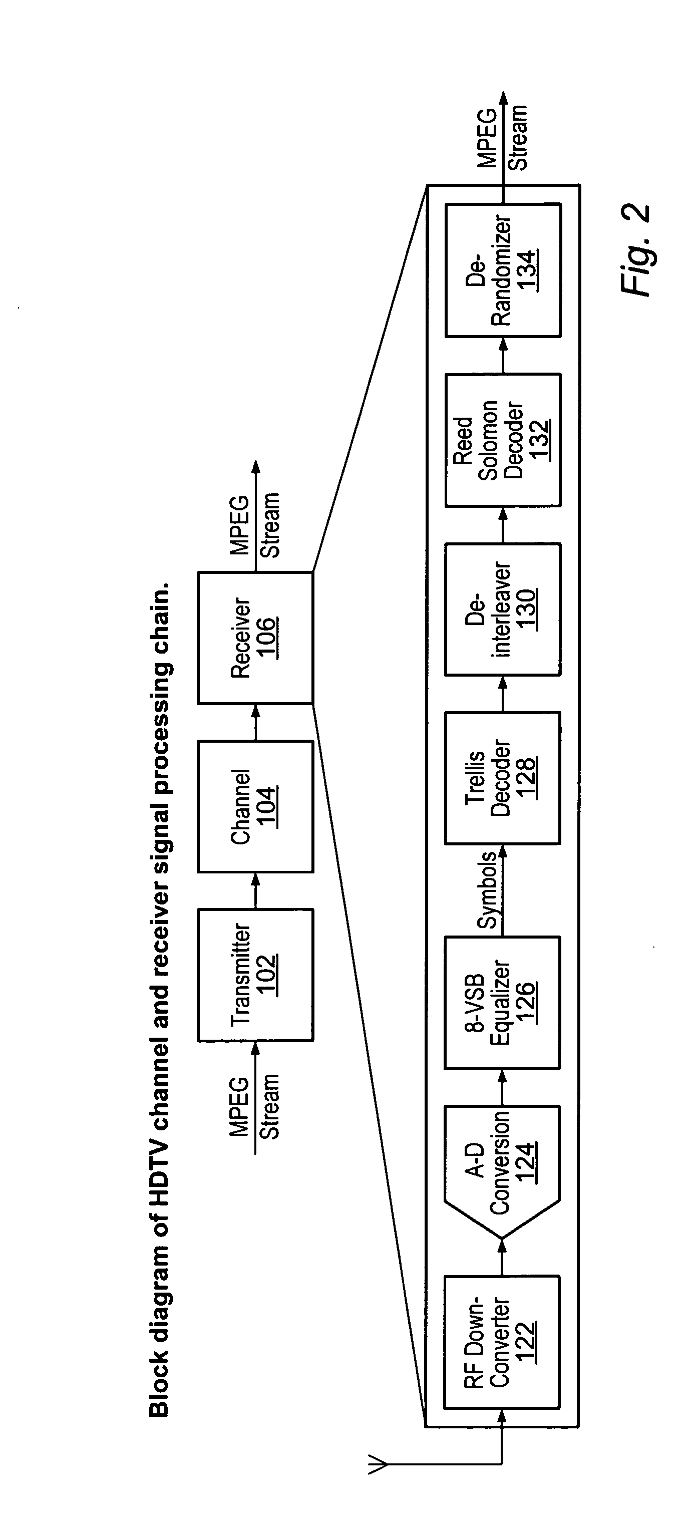
[0045] FIGS. 1A-B: Communication System FIGS. 1A and 1B illustrate an exemplary communication system including a transmitter 102, a channel 104, and a receiver 106. As shown, the transmitter 102 may generate a signal which is intended to be received by the receiver 106. The signal generated by the transmitter 102 propagates through the channel 104 and is received by the receiver 106. As shown in FIG. 1A, as the signal propagates through the channel 104, the signal may experience various types of multipath distortion, including reflections from the ground or from various objects such as objects 108 and 110. Examples of various types of objects that can introduce multipath distortion include buildings, homes, vehicles, airplanes, and natural phenomena such as non-level terrain, trees, etc. This multipath distortion may result in various echoes being received by the receiver 106.

[0046]FIG. 1B suggests that a direct path between the transmitter and receiver may be occluded. Thus, the “...


PUM


Abstract

A system and method for estimating a channel spectrum. The method includes: (a) receiving an input signal from a channel, where the input signal includes one or more major echoes and zero or more minor echoes introduced by the channel; (b) identifying the one or more major echoes present in the input signal; (c) identifying the minor echoes from a filtered autocorrelation function of the input signal in response to a determination that there is only one major echo; (d) identifying the minor echoes from a filtered power spectrum of the input signal in response to a determination that there is more than one major echo; (e) computing a channel spectrum estimate from the major echoes and minor echoes; where the channel spectrum estimate is usable to remove at least a portion of the one or more major echoes and one or more minor echoes from the input signal.

Description

PRIORITY DATA [0001] This application claims the benefit of priority of U.S. Provisional Application No. 60 / 396,819 filed on Jul. 18, 2002, entitled “Frequency Domain Equalization Algorithm”, invented by William H. Hallidy, Jr. and Jan D. Garmany. This provisional application is hereby incorporated by reference in its entirety as though fully and completely set forth herein.BACKGROUND OF THE INVENTION [0002] 1. Field of the Invention [0003] The present invention relates generally to the field digital telecommunication, and more particularly to an adaptive equalization method for eliminating echoes at the receiver of a communication channel. [0004] 2. Description of the Related Art [0005] Many systems utilize wireless transmission of signals, including wireless telephone systems, wireless television systems, and other systems which perform wireless communication. Such systems generally include at least one transmitter which transmits signals through a channel to at least one receiver...

Claims


Application Information

Patent Timeline
IPC IPC(8): H04B7/005H04L27/26
CPCH04B7/005H04L27/2647H04L27/2613
Inventor GARMANY, JAN D.HALLIDY, WILLIAM H.
Owner COHERENT LOGIX
Learn More