Gas turbine blade cooling circuit having a cavity with a high aspect ratio

a cooling circuit and turbine blade technology, applied in the field of turbine blade cooling circuits, can solve the problems of limiting the life of the blade, the cooling circuit is unsuitable for the blade that is “long, and the air flow rate is small, so as to achieve effective cooling, reduce the drawbacks, and facilitate fabrication

Active Publication Date: 2005-11-24
SN DETUDE & DE CONSTR DE MOTEURS DAVIATION S N E C M A
View PDF7 Cites 7 Cited by
  • Summary
  • Abstract
  • Description
  • Claims
  • Application Information

AI Technical Summary

Benefits of technology

[0007] A main object of the invention is thus to mitigate such drawbacks by proposing a cooling cavity for a gas turbine blade, and more particularly a blade of the “long and thin” type, enabling the blade to be cooled effectively and that is easy to fabricate.

Problems solved by technology

For example, in a high pressure turbine, the temperature of the gas coming from the combustion chamber reaches values well above those that can be withstood without damage by the moving blades of the turbine, which has the consequence of limiting their lifetime.
Nevertheless, those cooling circuits are unsuitable for blades that are “long and thin”, i.e. blades presenting a thickness (maximum distance between the pressure side face and suction side face of the blade) that is considerably smaller than their radial height (distance between the root and the tip of the blade).
One of the constraints associated with such blades is the small air flow rate available for cooling them.
Since such a modification is not sufficient for cooling the blade, it is also necessary to disturb the internal flow, e.g. by means of spike or bridge type flow disturbers.
Nevertheless, the use of conventional disturbers is made impossible by the fineness of the cooling cavity in such blades.
In particular, the presence of spikes in the cooling cavity impedes the flow of air passing therethrough excessively and leads to reduced mechanical strength which is a source of crack starters.
Bridges also raise problems of fabrication when casting blades.

Method used


Image

  • Gas turbine blade cooling circuit having a cavity with a high aspect ratio
  • Gas turbine blade cooling circuit having a cavity with a high aspect ratio
  • Gas turbine blade cooling circuit having a cavity with a high aspect ratio

Examples


Embodiment Construction

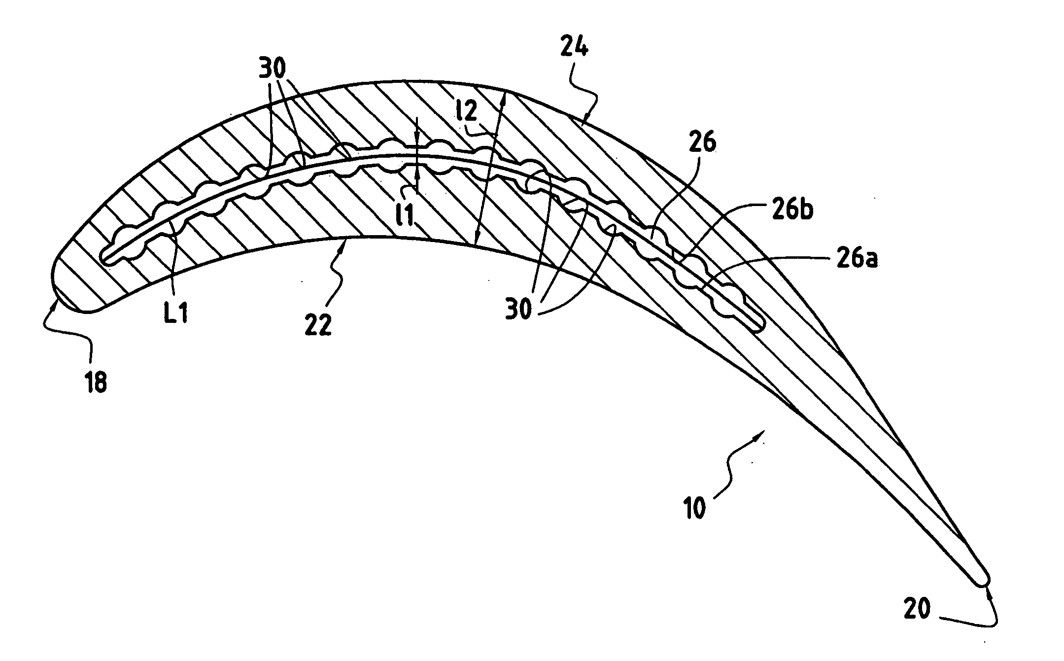
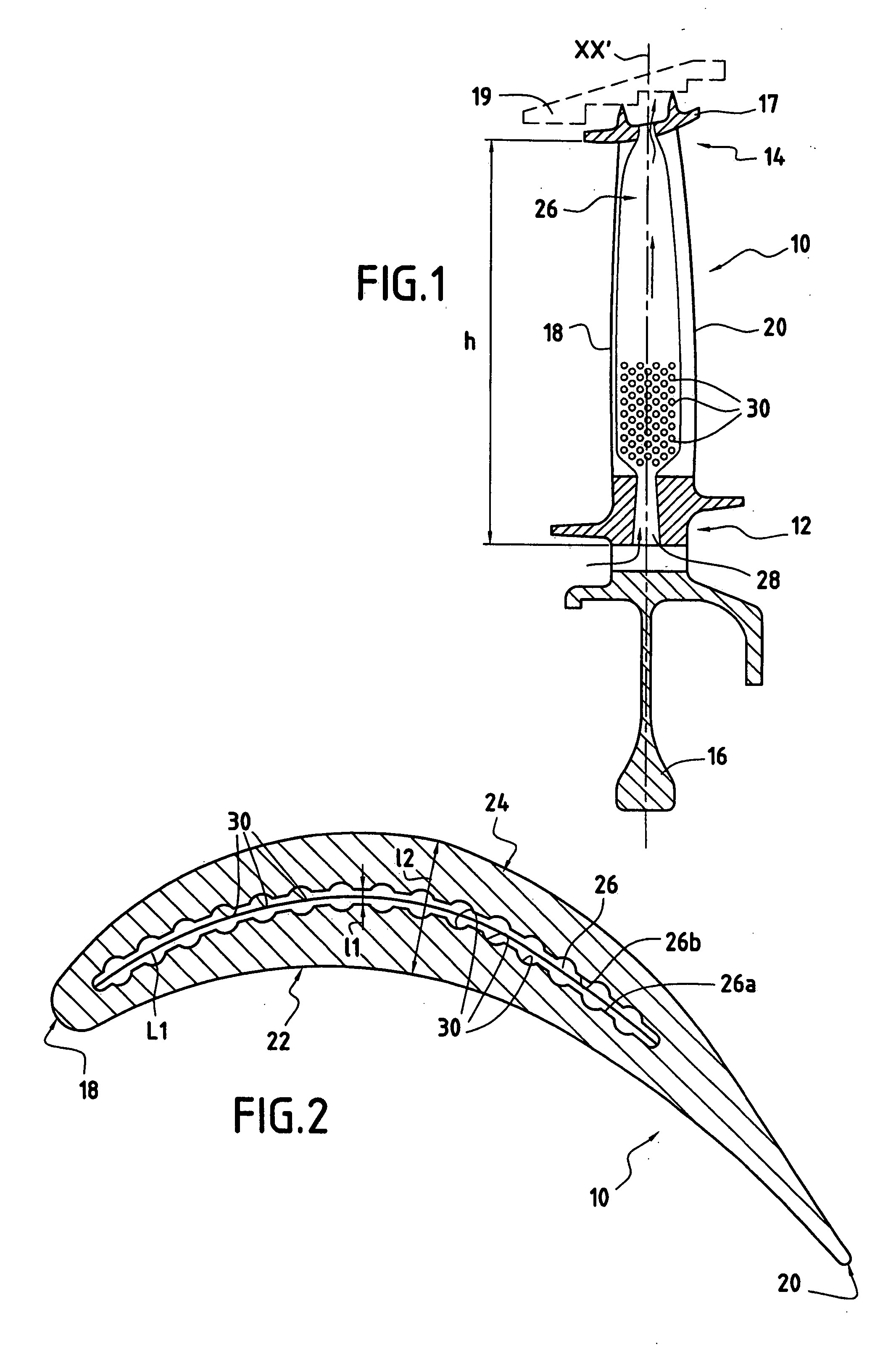
[0022] The blade 10 having a radial axis XX′ and shown in FIGS. 1 and 2 is a moving blade of a high pressure turbine in a turbomachine. Naturally, the invention can also be applied to other blades in the turbomachine, for example to the blades of its low pressure turbine.

[0023] The blade 10 comprises an airfoil surface (or blade proper) which extends radially between a blade root 12 and a blade tip 14. The blade root 12 is for mounting on a disk 16 of the rotor of the high pressure turbine. As shown in FIG. 1, the blade tip 14 may have sealing wipers 17 disposed facing an abradable covering 19 fitted to the casing (not shown) of the high pressure turbine.

[0024] The airfoil surface presents four distinct zones: a leading edge 18 disposed facing the flow of hot gas coming from the combustion chamber of the turbomachine; a trailing edge 20 remote from the leading edge 18; a pressure side face 22; and a suction side face 24, these side faces 22 and 24 interconnecting the leading edge ...


PUM


Abstract

A blade for a turbomachine gas turbine, the blade having a cooling circuit comprising at least one cooling cavity with a high aspect ratio extending radially between a root and a tip of the blade, and at least one air admission opening at a radially inner end of the cavity to feed it with cooling air, at least one of the walls of the cooling cavity being provided with a plurality of indentations so as to disturb the flow of cooling air in said cavity and increase heat exchange.

Description

BACKGROUND OF THE INVENTION [0001] The present invention relates to the general field of cooling blades in turbomachine gas turbines. More particularly it seeks to improve the cooling of a blade provided with a cooling cavity having a high aspect ratio. [0002] It is known to provide the moving blades of a turbomachine gas turbine, such as the high and low pressure turbines, with internal cooling circuits enabling them to withstand without damage the very high temperatures to which they are subjected while the turbomachine is in operation. For example, in a high pressure turbine, the temperature of the gas coming from the combustion chamber reaches values well above those that can be withstood without damage by the moving blades of the turbine, which has the consequence of limiting their lifetime. [0003] By means of internal cooling circuits, air which is generally injected into the blade by its root, travels along the blade, following a path formed by cavities made inside the blade,...

Claims


Application Information

Patent Timeline
Patent Type & Authority Applications(United States)
IPC IPC(8): F01D5/18F02C7/18
CPCF05D2260/2214F01D5/187
Inventor DAUX, STEPHANGIOT, CHANTALJOUBERT, HUGUESSAUTHIER, BENJAMIN
Owner SN DETUDE & DE CONSTR DE MOTEURS DAVIATION S N E C M A
Why Eureka
Try Eureka