SRAM core cell for light-emitting display

Inactive Publication Date: 2005-11-24
SAMSUNG DISPLAY CO LTD
View PDF7 Cites 36 Cited by
  • Summary
  • Abstract
  • Description
  • Claims
  • Application Information

AI Technical Summary

Benefits of technology

[0035] In one embodiment, the present invention arranges transistors in sequence so as to form a polysilicon layer or channels forming the transistors in an oblique direction in a defined region in

Problems solved by technology

In the CMOS RAM core cell according to prior art, a plurality of NMOS and PMOS transistors must be formed with a predetermined width and a prede

Method used


Image

  • SRAM core cell for light-emitting display
  • SRAM core cell for light-emitting display
  • SRAM core cell for light-emitting display

Examples


Embodiment Construction

[0044] Hereinafter, a SRAM core cell for a light-emitting display according to an embodiment of the present invention will be described in detail with reference to the accompanying drawings.

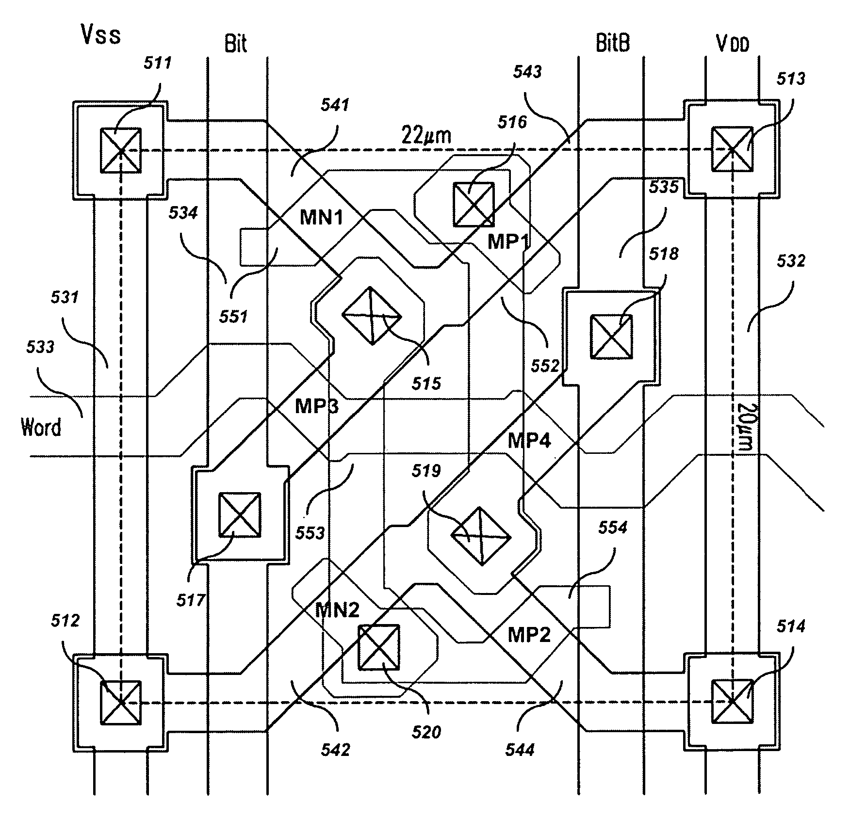
[0045] Referring to FIG. 4, a SRAM core cell includes two flip-flop circuits for memory (e.g., MP1 and MN1, and MP2 and MN2), and two switches (e.g., MP3 and MP4). By applying pulses to word lines to turn a cell transistor on, data transfer is activated between a bit line pair (“Bit” and “Bitb”) and flip-flops. When writing data, a high voltage is applied to one side of the bit line pair, a low voltage being applied to the other side. This is transferred to a memory node (a common source / drain node of MP1 and NM1, and a common source / drain node of MP2 and MN2) to memorize binary information. When reading data, a voltage sustained at the bit line pair is detected in correspondence to the voltage of nodes and transferred to the exterior. Unlike the DRAM, the SRAM stores data without a refresh oper...


PUM


Abstract

A SRAM core cell for a light-emitting display applicable to a data driver of an organic electro-luminescence light-emitting display device includes thin film transistors as a data memory for a data driver of the light-emitting display. The SRAM core cell also includes switching transistors and data memory transistors. The switching transistors are coupled to a bit line and a word line to select data writing or reading. The data memory transistors are coupled to a power voltage or a ground voltage to enable data writing and reading. The bit line and the word line are formed in first and second directions. The channels of the switching transistors and the data memory transistors are formed in an oblique direction with respect to the first and second directions.

Description

CROSS REFERENCE TO RELATED APPLICATION [0001] This application claims priority to and the benefit of Korean Patent Application No. 10-2004-0036868 filed on May 24, 2004 in the Korean Intellectual Property Office, the entire content of which is incorporated herein by reference. BACKGROUND OF THE INVENTION [0002] (a) Field of the Invention [0003] The present invention relates to a static RAM (SRAM) core cell. More specifically, the present invention relates to a SRAM core cell for a light-emitting display, and is applicable to a data driver of an organic electro-luminescence (EL) light-emitting display device. [0004] (b) Description of the Related Art [0005] The organic EL light-emitting display is a device for displaying an image by controlling a current flowing to an organic material that emits light when the current flows to it. In the organic EL light-emitting display, the organic material is divided by pixels and arranged in a matrix form. The organic EL light-emitting display is...

Claims


Application Information

Patent Timeline
IPC IPC(8): G09G3/20H01L51/50G09G3/30G09G3/32G11C11/41G11C11/412G11C11/419H01L21/8244H01L27/02H01L27/11H01L29/786H05B33/00H05B33/14
CPCG09G3/3225G09G3/3275H01L27/1108H01L27/0207H01L27/11G11C11/412H10B10/125H10B10/00F24F13/24F24F2013/245
Inventor YOON, HAN-HEE
Owner SAMSUNG DISPLAY CO LTD
Why Eureka
Try Eureka