Intra-body flow distributor for heat exchanger

a distributor and heat exchanger technology, applied in indirect heat exchangers, machines/engines, lighting and heating apparatus, etc., can solve the problems of increasing the chance of certain tubes being plugged, the velocity of process gas is greater than ideally desired, and the product in the process gas leaving the furnace is not stable, etc., to achieve the effect of improving the gas flow distribution

Inactive Publication Date: 2005-12-01
KNIGHTHAWK ENG
View PDF14 Cites 12 Cited by
  • Summary
  • Abstract
  • Description
  • Claims
  • Application Information

AI Technical Summary

Benefits of technology

[0012] A method for improving the distribution of gas flow in an existing process heat exchanger system is disclosed. The existing process heat exchanger system includes gas flow piping and a heat exchanger input section. The method includes modeling the gas flow characteristics of the existing process heat exchanger system and thereby optimizing the shape of the refractory in the heat exchanger input section based on the gas flow characteristics. Next, the size and orientation of a flow distributor having a nose cone and one or more diverting rings is optimized to substantially evenly distribute the process gas at the tube sheet of the existing process heat exchanger system. The size and orientation of the nose cone is optimized to distribute any centrally located jet of gas. To optimize the nose cone, a position along a central axis of the input section, a diameter, an axial expanse, or a surface curvature of the nose cone can be iteratively determined. The size and orientation within the input section of a first diverter ring can be optimized to divert at least a portion of the gas flow distributed by the nose cone into the shadow of the nose cone. To optimize the first diverter ring, a radius, a width, a relative separation from the nose cone, or an angular orientation of the first diverter ring can be iteratively determined. The size and orientation within the input section of a second diverter ring can be optimized to redirect gas flow toward and away from the second diverter ring. Using more than one diverter ring within the input section can be based on the size of the input section or the characteristics of the gas flow. An assembly is then fabricated that includes the nose cone and diverter ring(s). The assembly is installed in the input section of the existing process heat exchanger system for substantially evenly distributing the process gas.

Problems solved by technology

The products in the process gas leaving the furnace are not stable at the high temperature at the outlet of the furnace.
Due to the recirculation, the process gas may be poorly distributed at the face of the tube sheet, and the velocity of the process gas is greater than ideally desired.
In addition, recirculation can cause fouling on certain portions of the tube sheet 38, for example the outer edge, so that the chances of plugging of certain tubes 34 are increased.
Such fouling conditions decrease the efficiency of the system.
As is known in the art, film boiling can cause the welded joint of the tubes 34 to the sheet to fail and can exacerbate corrosion at the welded joint.
Unfortunately, the intense heat of the process gas in the inlet section 22 can quickly destroy any such coatings.
Because the heat of the process gas is so intense, the equipment used to break up the flow can be quickly destroyed, which can lead to additional problems.

Method used


Image

  • Intra-body flow distributor for heat exchanger
  • Intra-body flow distributor for heat exchanger
  • Intra-body flow distributor for heat exchanger

Examples


Embodiment Construction

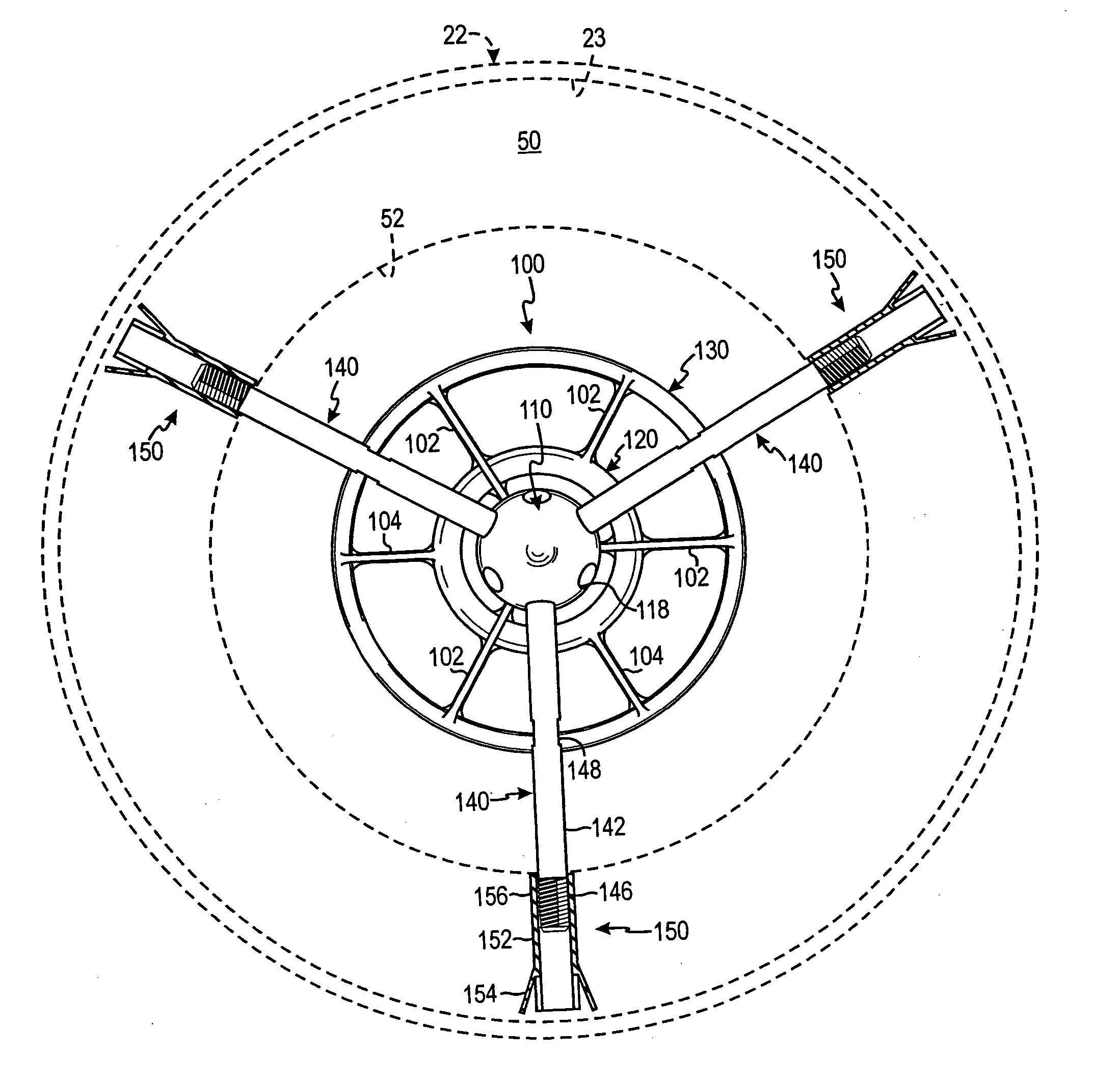
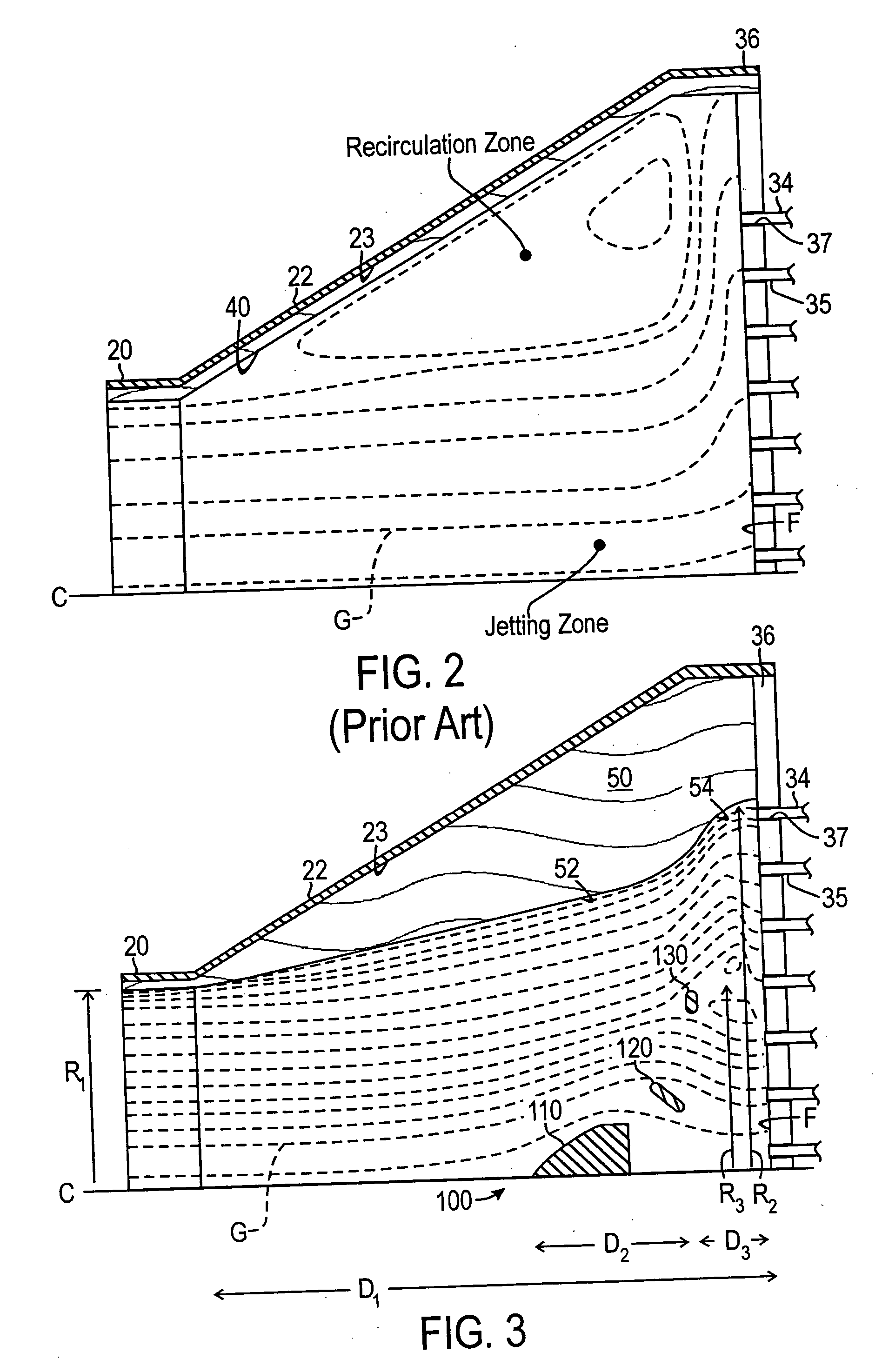
[0024] Referring to FIG. 3, a flow distributor 100 according to certain teachings of the present disclosure is schematically illustrated. The flow distributor 100 is installed in an inlet section 22 connected to a transfer line heat exchanger similar to that described previously for use in quenching stages of a thermal cracking process. Although the present embodiment of the flow distributor 100 is discussed for use in such a thermal cracking process in the present disclosure, one of ordinary skill in the art will appreciate that teachings of the present disclosure can be used for a number of applications having flow of a fluid.

[0025] The flow distributor 100 distributes the process gas from the furnace piping 20 and inlet section 22 into the transfer line heat exchanger of a process system. As noted above, the transfer line heat exchanger (not shown) includes a tube sheet 36 having a plurality of holes 37 for passage of the process gas into transfer tubes 34 of the heat exchanger....


PUM


Abstract

A flow distributor for mounting in an inlet of a heat exchanger includes a nose cone and one or more diverting rings. The nose cone is aerodynamically shaped to divert impingent gas flow around the nose cone. A first diverting ring is spaced outwardly from the nose cone and can be oriented such that at least a portion of the gas flow diverted by the nose cone is redirected into the wake of the nose cone. A second diverting ring can be spaced outwardly from the first diverting ring and can be oriented to divert gas flow impingent thereon. Struts connect the nose cone and one or more rings. Refractory on the wall of the inlet is shaped to reduce the recirculation at the outer perimeter thereof. The flow distributor is installed in the inlet with refractory to achieve substantially equal flow across the tube sheet of the heat exchanger.

Description

FIELD OF THE INVENTION [0001] The subject matter of the present disclosure relates generally to a device for distributing gas flow in a pipe that feeds the gas into a heat exchanger. More particularly, the subject matter of the present disclosure relates to a flow distributor mounted in an inlet section of a transfer line heat exchanger for evenly distributing gas flow to a tube sheet of the heat exchanger. BACKGROUND OF THE INVENTION [0002] Thermal cracking of hydrocarbons is a large-scale process for the production of light olefins, such as ethylene and propylene, which are major building blocks of the petrochemical industry. Referring to FIG. 1, a portion of a thermal cracking process is schematically illustrated. Feedstock, such as naphtha, methane, ethane, propane, or butane, is cracked in a pyrolysis or cracking furnace (not shown) to generate light hydrocarbons. The process gas leaves the furnace at temperatures ranging from 750 to 900° C. (1400 to 1650° F.) and at pressures ...

Claims


Application Information

Patent Timeline
Patent Type & Authority Applications(United States)
IPC IPC(8): B01J4/00B01J19/24F28D7/16F28F27/02
CPCB01J4/001B01J19/2425F28F9/0265F28D7/16B01J2219/00085
Inventor KNIGHT, CLIFTON TROYLOWRY, DAVID RAYMONDCORRY, JUDETH BRANNONWILLIAMS, KENNETH ROY JR.
Owner KNIGHTHAWK ENG
Why Eureka
Try Eureka