Eureka AIR delivers breakthrough ideas for toughest innovation challenges, trusted by R&D personnel around the world.

Ring bearing network and method of implementing service bearing thereof

Inactive Publication Date: 2005-12-01
HUAWEI TECH CO LTD
View PDF33 Cites 35 Cited by
  • Summary
  • Abstract
  • Description
  • Claims
  • Application Information

AI Technical Summary

Benefits of technology

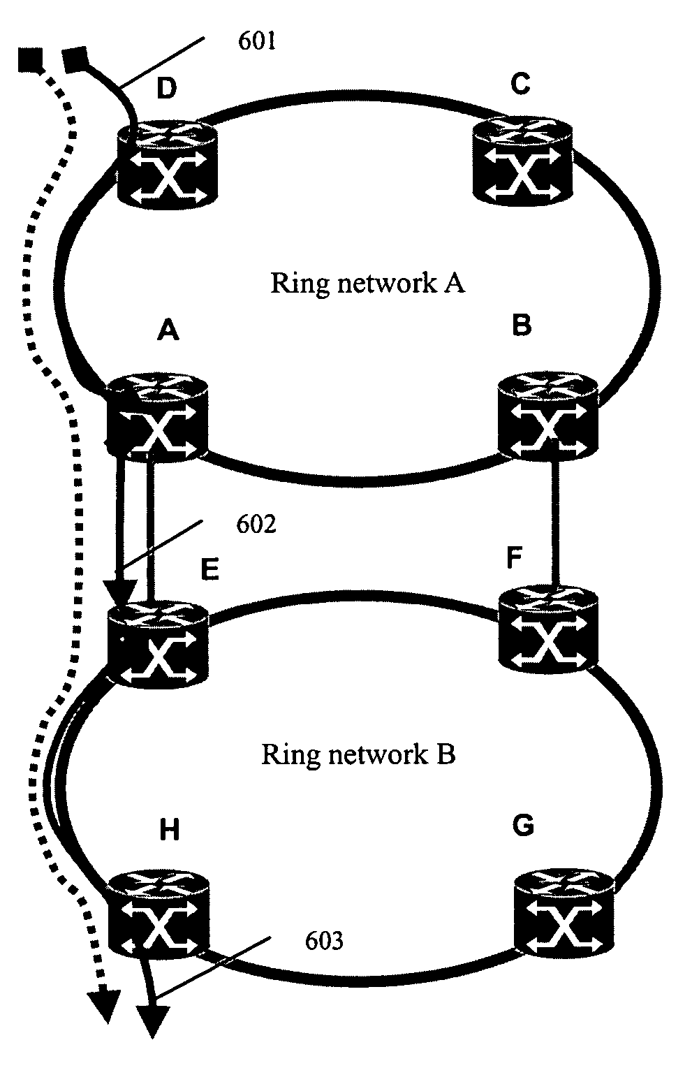
[0007] An object of the present invention is to provide a ring bearing network and a method of implementing service bearing thereof, for implementing ring network in a simple and effective way, resolving interconnection and protection of service data across rings, and improving bandwidth utilization efficiency of ring network.
[0042] It can be seen from above technical solution of the present invention that the ring bearing network of the present invention not only has all functions of the RPR network, but also provides the following advantages when compared to RPR network: it doesn't perform Media Access Control, and therefore it is simpler in processing and improves processing efficiency of data transmission and utilization efficiency of bandwidth of ring network; since it employs standard MPLS frame format, the service data format is independent of the ring network, and therefore cross-ring end-to-end service provision as well as ringlet interconnection in the case of multi-ring intersecting / inter-tangent can be implemented in the ring bearing network of the present invention without any auxiliary technology; since MPLS encapsulation technology is employed on the ring bearing network, different QoS parameters can be assigned for different Label Switched Paths (LSPs), and therefore more Service Level Agreements (SLAs) can be supported, differentiated QoS can be assured and supported better through scheduling LSP granularity with pre-negotiated QoS parameters; furthermore, the Operation And Maintenance (OAM) functions, including LSP Connectivity Verification (CV), LSP Fast Failure Detect (FFD), Forward Defect Indication (FDI), and Backward Defect Indication (BDI), etc., in MPLS can be utilized fully.

Problems solved by technology

However, RPR technology has its limitations: IEEE802.17 only defines the RPR MAC layer technology designed for a single physical ring or logical ring (a Virtual Container (VC) channel across multiple SDH physical rings), but RPR uses a dedicated frame format, which can not be identified by any other device outside of the RPR network; therefore, RPR is not a total solution for the entire network and is only applicable to single ring networking; in cross-ring scenarios, it has to be terminated with R-MAC (Resilient Packet Ring-Media Access Control) and can not provide end-to-end bandwidth sharing, fairness mechanism, or Quality of Service (QoS) assurance and protection for inter-ring services.
As the result, a Multi-Service Provisioning Platform (MSPP) with purely embedded RPRs has certain limitations on topology when it is used to establish a complex network and has to be supplemented with other technologies to provide end-to-end service provision.
At present, a general solution is to introduce Layer-2 / Layer-3 switches at entries / exits of rings and between rings to implement service data interconnection between RPRs, which increases network complexity and makes network structure unclear.
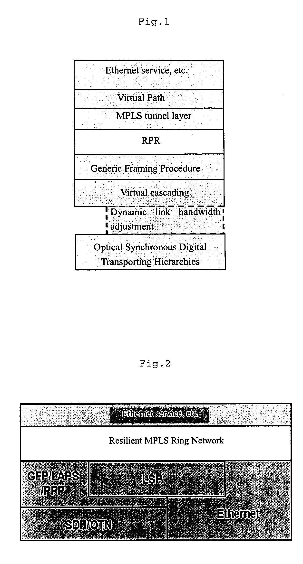
Another solution is to overcome RPR's disadvantages with MPLS over RPR; however, this approach introduces two protocol layers: RPR layer and Multi Protocol Label Switching (MPLS) layer, as shown in FIG. 1, which increases complexity of service data processing and network Operation Administration and Maintenance (OAM), and degrades processing efficiency; in addition, due to the special frame format of RPR, introduction of MPLS layer will increase overhead on each data packet and thereby degrade utilization efficiency of network bandwidth.

Method used


Image

  • Ring bearing network and method of implementing service bearing thereof
  • Ring bearing network and method of implementing service bearing thereof
  • Ring bearing network and method of implementing service bearing thereof

Examples


Embodiment Construction

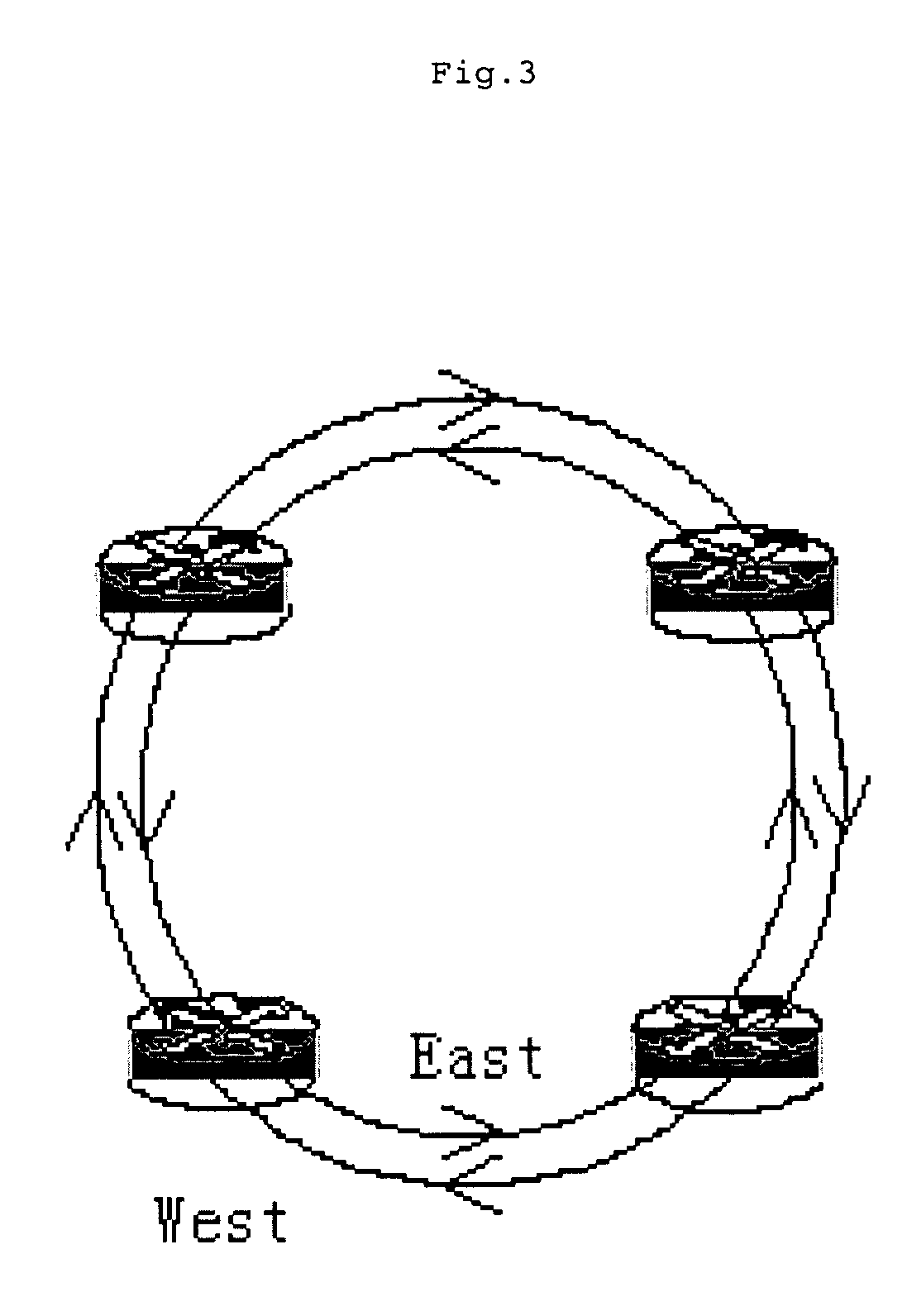
[0050] The core of the present invention is to establish a ring bearing network (resilient MPLS ring network) directly at the Multi Protocol Label Switching (MPLS) layer, independent of the Resilient Packet Ring (RPR) layer; the hierarchy in which the ring network is located in the MSPP is shown in FIG. 2; the ring network is independent of the physical layer; it may employ different physical layer technologies as required or be borne directly on logical links. The network topology of the ring network is shown in FIG. 3, comprises a plurality of network nodes and employs a double-ring structure, composed of a west ring and an east ring; wherein, the west ring transports service data in clockwise, while the east ring transports service data in counter clockwise; different nodes are connected with each other through physical links, for bearing client service data between them in a manner of label switched path; said nodes receive or transmit data encapsulated in standard Multi Protoco...


PUM


Abstract

The present invention discloses a ring bearing network and a method of implementing service bearing thereof; said ring bearing network comprises a plurality of network nodes and physical links or logical links connected the network nodes, designed to bear service data at different nodes in a manner of label switched path; said method of implementing service bearing based on said ring bearing network comprises: scheduling multi protocol label switching service data at the node onto said ring bearing network with a predetermined scheduling algorithm at the service source node; multiplexing the service data at different nodes in the same physical link or logical link in a manner of label switched path for transporting; scheduling the respective service data in said physical link or logical link off said ring bearing network at the service destination node. The present invention can make service processing in ring network simpler and more efficient, implement cross-ring service data interconnection and protection, and improve bandwidth utilization ratio of the rings.

Description

FIELD OF THE INVENTION [0001] The present invention relates to the technical field of service bearing in network communication, particularly to a ring bearing network and a method of implementing service bearing thereof. BACKGROUND OF THE INVENTION [0002] As communication service bearing network technologies develop, new generations of metropolitan area bearing network technologies emerges endlessly; wherein, Resilient Packet Ring (RPR) technology, characterized by technical sophistication, effectiveness of investment, superior performance, and extensive support to services, provides a good solution for metropolitan area bearing networks. [0003] RPR network is a bearing network generated on the basis of requirements of packet-based metropolitan area network; it is a ring network composed of packet switching nodes, with adjacent nodes connected through a pair of reverse physical paths; its network topology is based on two reverse transmission rings, wherein, the ring that transmits d...

Claims


Application Information

Patent Timeline
IPC IPC(8): H04L12/28H04L12/413H04L12/42H04L12/46H04L12/56
CPCH04L12/2852H04L12/42H04L45/50H04L45/00H04L12/4637
Inventor WAN, HUAIXUE
Owner HUAWEI TECH CO LTD
Why Eureka
Eureka Blog
Learn More