Apparatus, system and method for an adiabatic coupler for multi-mode fiber-optic transmission systems

a multi-mode fiber-optic transmission system and adiabatic coupler technology, applied in the field of fiber-optic communication systems, can solve the problems of low bandwidth of mmf, limited bandwidth of existing, and support transmission at relatively low speeds, so as to improve system bandwidth, reduce overall device cost, and reduce insertion loss

Inactive Publication Date: 2005-12-01
OCLARO NORTH AMERICA
View PDF2 Cites 99 Cited by
  • Summary
  • Abstract
  • Description
  • Claims
  • Application Information

AI Technical Summary

Benefits of technology

[0015] The present invention provides a multi-mode fiber optical communications system utilizing an MMF to SMF coupler with very low insertion loss. Applying such couplers into a high data rate MMF transmission system not only significantly improves the system bandwidth, but also relaxes the requirements for the optical components and thus lowers the overall device cost. A first embodiment of a fiber-optic communications system in accordance with the present invention comprises a multi-mode waveguide carrying an optical signal, a single-mode waveguide optically coupled to and receiving the optical signal from the multi-mode waveguide and an adiabatic coupler optically coupled between the multi-mode waveguide and the single-mode waveguide. Another embodiment of a fiber-optic communications system in accordance with the invention comprises a transmitter providing an optical signal, a single-mode waveguide optically coupled to and receiving the optical signal from the transmitter, a multi-mode waveguide optically coupled to and receiving the optical signal from the single-mode fiber, and an adiabatic coupler optically coupled between the single-mode waveguide and the multi-mode waveguide. The multi-mode waveguide and the single-mode waveguide may be optical fibers, planar waveguides or any other suitable waveguide. The adiabatic coupler may comprise a tapered core surrounded by a cladding or, alternatively, may comprise a core surrounded by a cladding, wherein the refractive index of at least one of the core and the cladding varies over the length of the adiabatic coupler and the diameter of the core is either constant or non-constant. In another aspect, the invention is a method of fabricating an adiabatic coupler for coupling a multi-mode fiber to a single-mode fiber comprising the steps of (a) splicing an end of the multi-mode fiber to an end of the single-mode fiber; (b) heating the splice with a heat source; and (c) pulling apart the multi-mode fiber and the single-mode fiber while heating the splice such that the splice is drawn out into a region with a tapered core, the taper of the core configured such that a fundamental mode of a light will propagate adiabatically through the tapered core.

Problems solved by technology

However, MMF suffers from low bandwidth, and thus can only support transmission at relatively low speeds (tens to hundreds of megabits per second).
As 10 Gigabit Ethernet (10 GbE) is increasingly introduced into optical communications networks, the bandwidth limitation of the existing MMF links becomes a new challenge for a network designer to achieve a meaningful transmission distance.
As a result, adjacent pulses may overlap after a certain transmission distance such that the receiver cannot distinguish one pulse from another, introducing bit errors.
However, since replacing existing MMF is usually quite expensive, many enterprise customers decide to continue using the existing legacy MMF instead of switching to the new generation fiber.
This method is still under development and so far only works under certain limited conditions.
It also adds complexity and cost to the design of detectors and transceivers deployed in a system using MMF.
Unfortunately, if there should exist, in the fiber refractive index profile, a localized distinct peak or dip at the core center, which is normal in legacy MMF, the lowest order modes may have largely different propagation times when compared with higher order modes.
This results in increased mode dispersion and causes link failure.
Unfortunately, this technique only works for data transmission rates that are less than 1 to 2 Gbit / s.
Restricted mode launch alone (described above) is not an ultimate solution as it only works under certain conditions of uniform modal dispersion, whereas the modal dispersion along the legacy fiber is highly unpredictable.
Although the center launch scheme combined with mode filtering (FIG. 3) introduces little loss of the optical signal at the transmitter side, high attenuation is often observed at the receiving splice due to the mode field diameter mismatch from MMF to SMF.
However, due to the mismatch of the core diameters, it is expected that direct coupling from a MMF to a SMF will result in high attenuation.
Obviously, MMF to SMF coupling loss translates directly into power penalty, and demands a larger power budget in the design of a transmission system using MMF.

Method used


Image

  • Apparatus, system and method for an adiabatic coupler for multi-mode fiber-optic transmission systems
  • Apparatus, system and method for an adiabatic coupler for multi-mode fiber-optic transmission systems
  • Apparatus, system and method for an adiabatic coupler for multi-mode fiber-optic transmission systems

Examples


Embodiment Construction

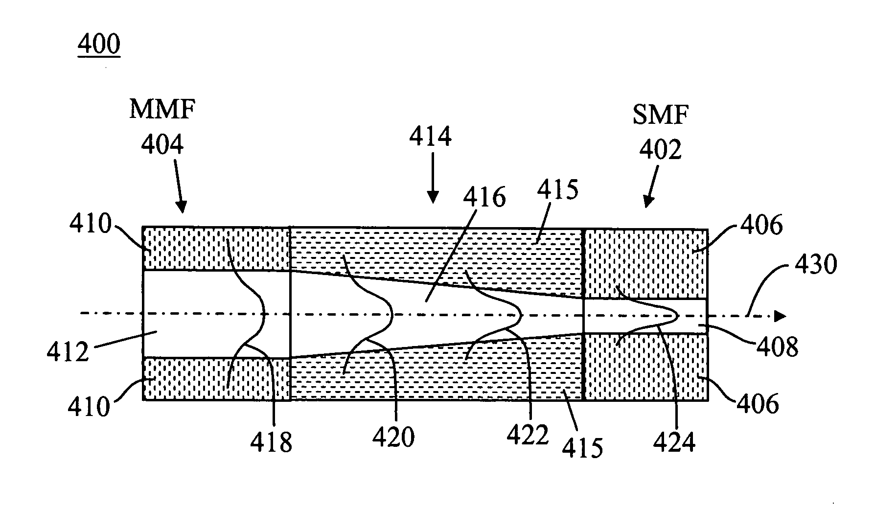
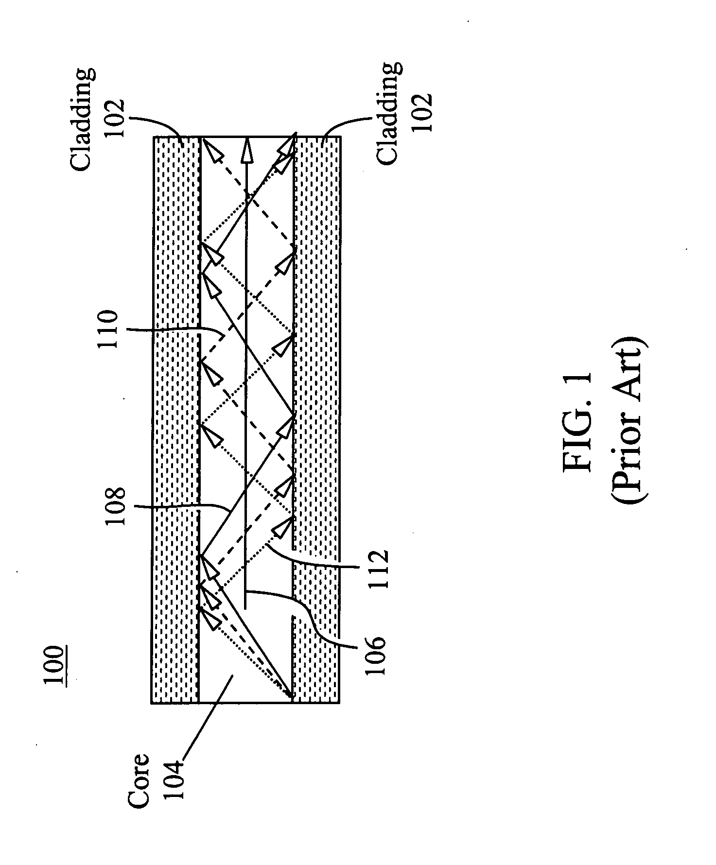
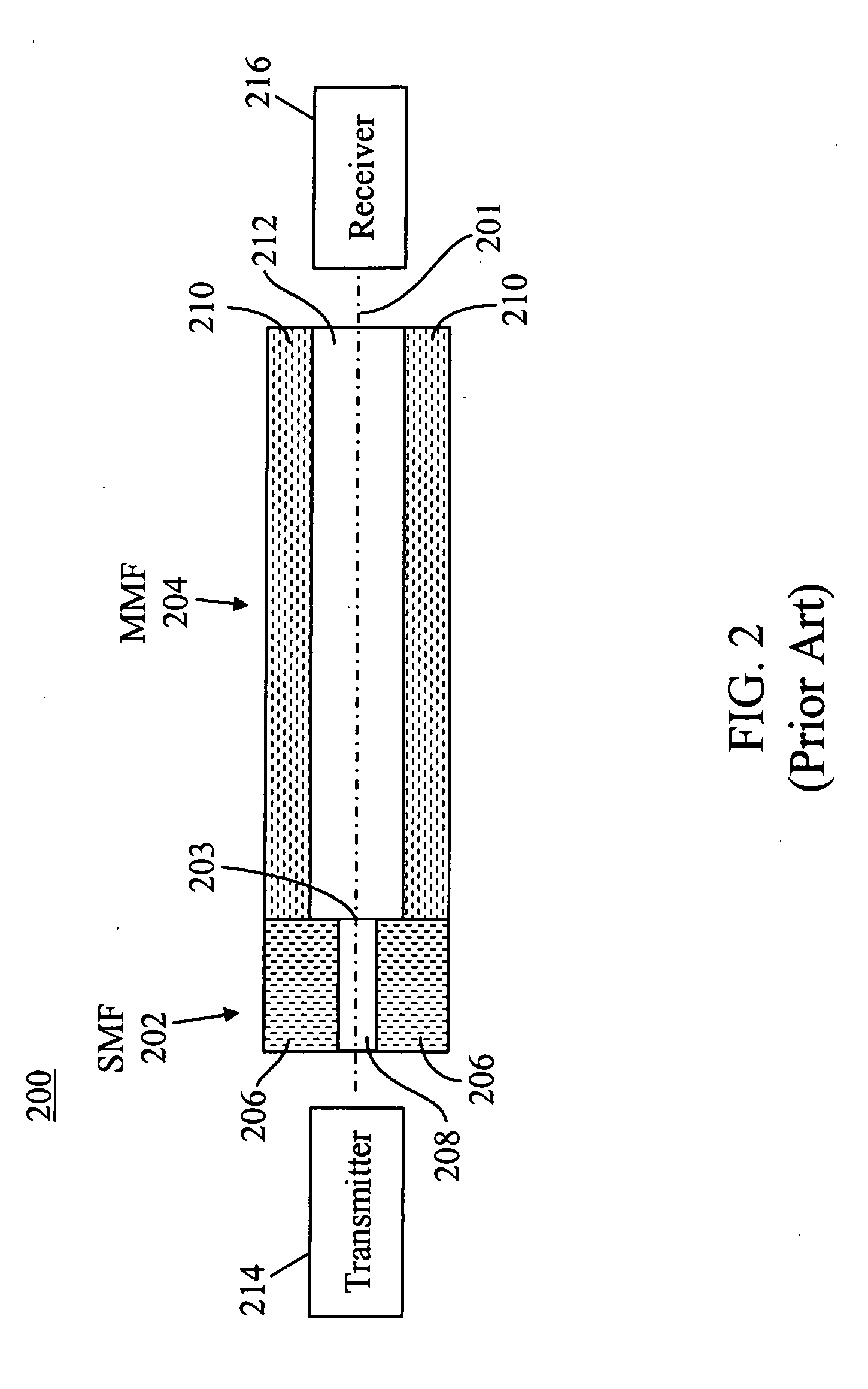
[0032] The present invention provides an improved apparatus and method for an adiabatic taper coupler for use within optical communications systems that utilize multi-mode optical fiber. The following description is presented to enable one ordinary skill in the art to make and use the invention and is provided in the context of a patent application and its requirements. Various modifications to the preferred embodiments will be readily apparent to those skilled in the art and the generic principles described herein may be applied to other embodiments. Thus, the present invention is not intended to be limited to the embodiments shown but is to be accorded the widest scope consistent with the principles and features described herein. In order to gain a detailed understanding of the invention, the reader is referred to the appended FIGS. 4-9 in conjunction with the following description. It is to be understood that the drawings are diagrammatic and schematic representations only and ar...


PUM


Abstract

An improved fiber-optic communications system comprises a multi-mode waveguide carrying an optical signal, a single-mode waveguide optically coupled to and receiving the optical signal from the multi-mode waveguide and an adiabatic coupler optically coupled between the multi-mode waveguide and the single-mode waveguide. The multi-mode and single-mode waveguides may be optical fibers. The adiabatic coupler may comprise a tapered core surrounded by a cladding. Alternatively, the adiabatic coupler may comprise a core surrounded by a cladding, wherein the refractive index of at least one of the core and the cladding varies over the length of the adiabatic coupler.

Description

CROSS-REFERENCE TO RELATED APPLICATION(S) [0001] This application relates to, and claims the priority benefit of, U.S. Provisional Patent Application No. 60 / 574,470 titled, “Apparatus, System and Method for an Adiabatic Coupler for Multi-Mode Fiber-Optic Transmission Systems,” filed on May 25, 2004. The subject matter of this related application is hereby incorporated by reference.FIELD OF THE INVENTION [0002] The present invention relates to fiber-optic communications systems. More particularly, the present invention relates to multi-mode fiber communications systems having a provision to filter selected modes so as to reduce modal dispersion and thereby increase system carrying capacity, defined as the product of bandwidth multiplied by distance. BACKGROUND OF THE INVENTION [0003] Many existing short-range optical fiber systems utilize multi-mode fiber (MMF). Multi-mode fiber has been widely used because of its low price, ease of installation, and its specification within several ...

Claims


Application Information

Patent Timeline
Patent Type & Authority Applications(United States)
IPC IPC(8): G02B6/028G02B6/14G02B6/255G02B6/26
CPCG02B6/0288G02B6/14G02B6/262G02B6/2552G02B6/2551
Inventor CAI, MINGBARBAROSSA, GIOVANNI
Owner OCLARO NORTH AMERICA
Why Eureka
Try Eureka