Optical transmission system, and trasmitter, receiver and signal level adjustment method for use therein

a transmission system and optical terminal technology, applied in the field of optical transmission systems, can solve the problems of increased size increased equipment costs, and increased costs of optical terminal devices b>802/b>

Inactive Publication Date: 2005-12-01
PANASONIC CORP
View PDF3 Cites 33 Cited by
  • Summary
  • Abstract
  • Description
  • Claims
  • Application Information

AI Technical Summary

Benefits of technology

[0014] According to the first aspect, desired-to-undesired-signal information is determined based on peak information concerning a frequency division multiplexed signal. Based on the desired-to-undesired-signal information, signal level information concerning a signal level for the frequency division multiplexed signal which ensures that the desired-to-undesired-signal information is equal to or greater than a predetermined level. Based on the signal level information, the signal level of the frequency division multiplexed signal when being converted to the optical signal is adjusted. Thus, there is provided an optical transmission system, more specifically, a sub-carrier multiplexing (SCM) optical transmission system where modulated signals are subjected to a frequency division multiplex before optical transmission, in which the level of the frequency division multiplexed signal is adjusted so that a spurious component occurring in the neighborhood of the spectrum of each modulated signal is reduced. As a result, it becomes possible to utilize the optical transmission path in an efficient manner.
[0040] Thus, based on the signal quality of each modulated signal, the signal level of the frequency division multiplexed signal is adjusted. As a result, the signal quality of the modulated signal can be maintained at a predetermined quality level.

Problems solved by technology

However, the above-described conventional transmission apparatus has a problem in that, due to the large size of the optical terminal device, there is a limit to the number of subscribers that can be accommodated, leading to high equipment costs, as described below.
As a result, the size of the optical terminal device 802 and the costs associated with the optical terminal device 802 are increased.
Thus, the optical terminal device 802, which is installed on the subscriber side, increases in size and the costs associated therewith increase thereby unfavorably affecting the economy of the overall transmission system.
However, in the case where such a modem is used to convert digital data signals to modulated signals and the modulated signals are subjected to a frequency division multiplex before being transmitted from the optical sending equipment (transmitter) to the optical terminal device (receiver), a spurious component occurs on both sides of the spectrum of each modulated signal at the electrical-to-optical conversion section, due to the non-linearity of an optical transmission system, in particular a semiconductor laser diode which is used as an electrical-to-optical conversion element.
Conventionally, no means has been provided for approximating and reducing such a spurious component.
In particular, spurious was difficult to approximate and reduce in the case where the modulation method changes over time.

Method used


Image

  • Optical transmission system, and trasmitter, receiver and signal level adjustment method for use therein
  • Optical transmission system, and trasmitter, receiver and signal level adjustment method for use therein
  • Optical transmission system, and trasmitter, receiver and signal level adjustment method for use therein

Examples


first embodiment

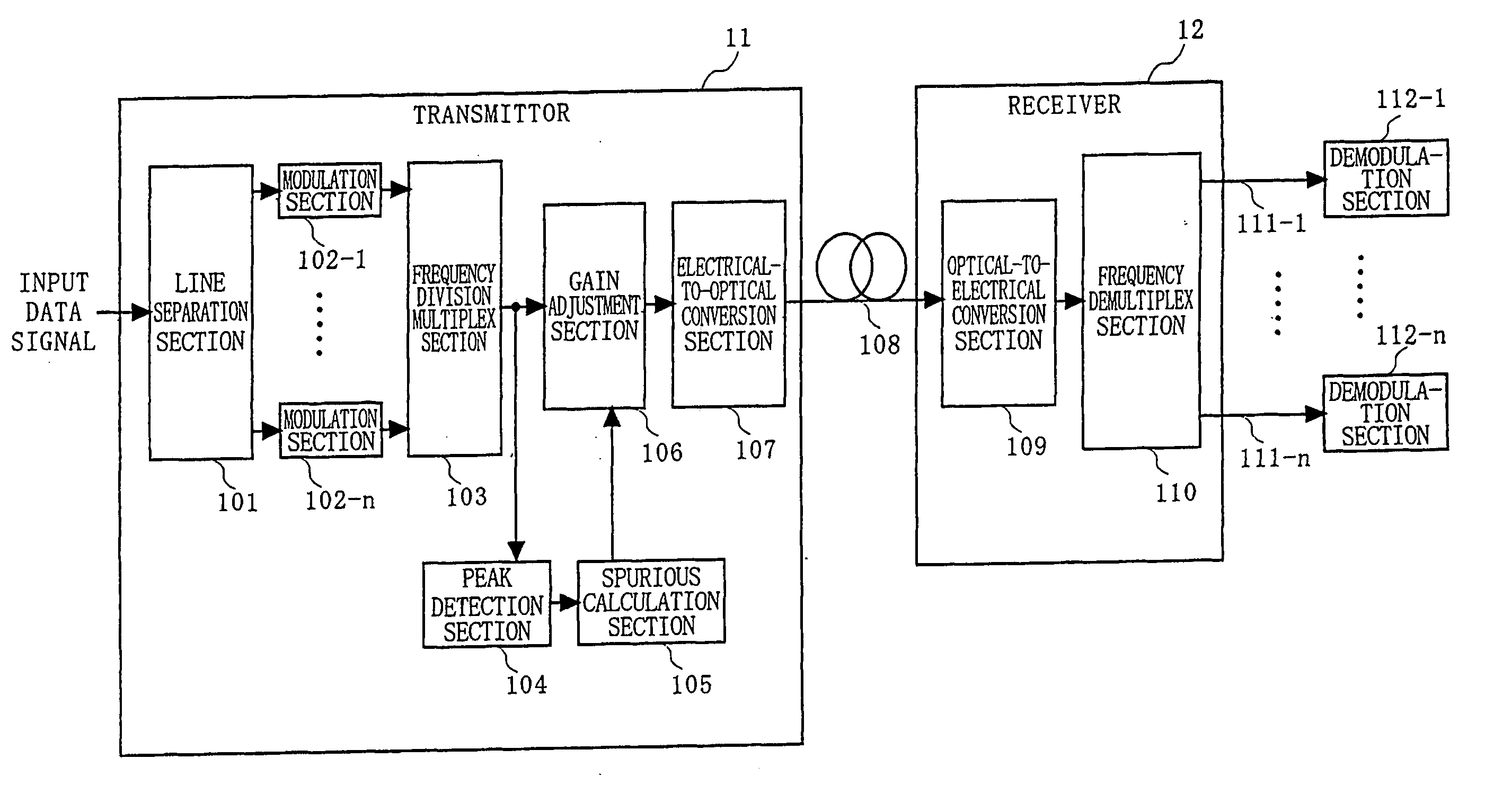
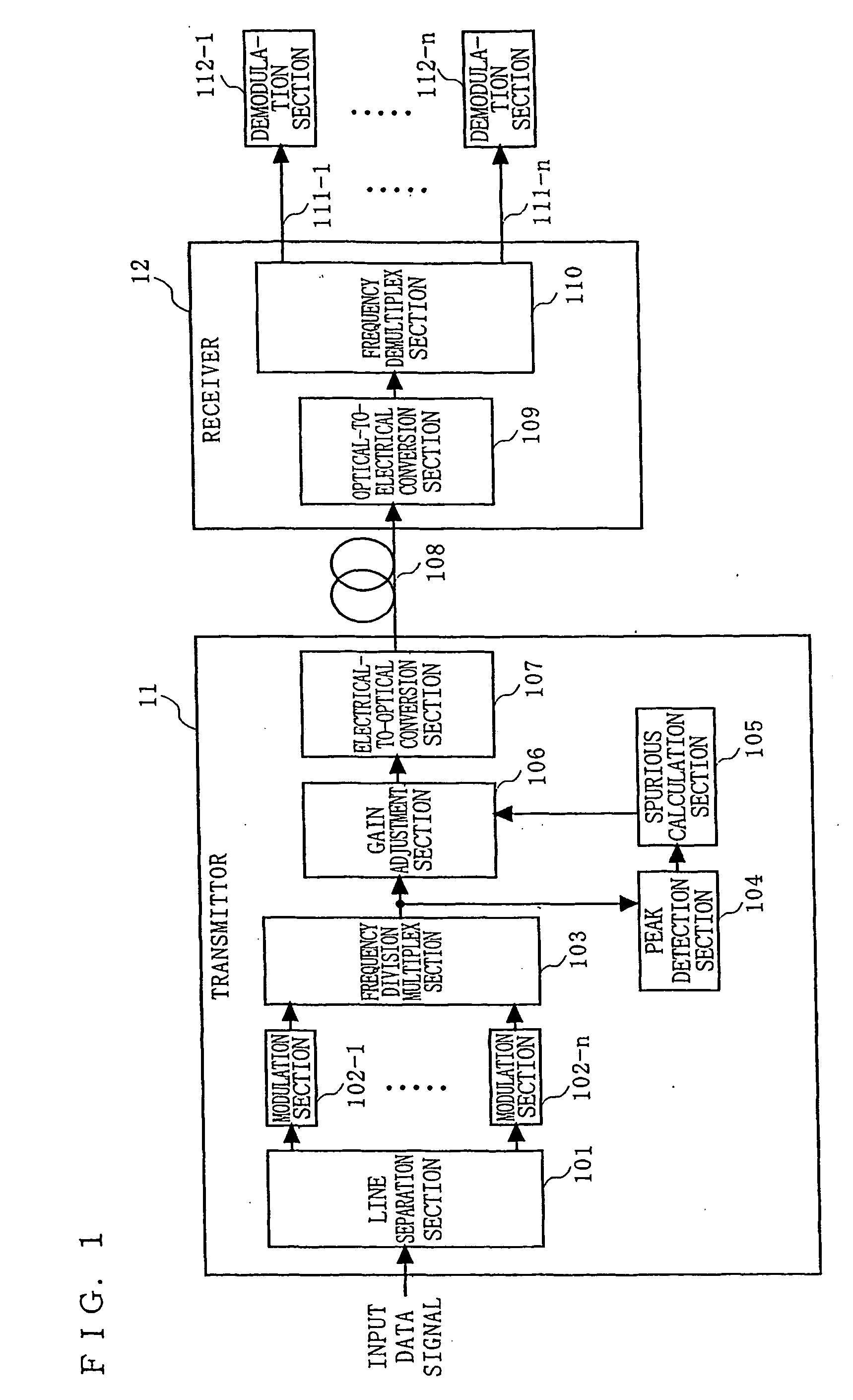
[0069]FIG. 1 is a block diagram illustrating the structure of an optical transmission system according to a first embodiment of the present invention. In FIG. 1, the optical transmission system comprises a transmitter 11, a first optical transmission path 108, a receiver 12, first to nth subscriber lines 111-1 to 111-n, and first to nth demodulation sections (terminal devices) 112-1 to 112-n. Herein, it is assumed that n is an integer which is equal to or greater than two.

[0070] The transmitter 11 is connected to the receiver 12 via the first optical transmission path 108. The transmitter 11 may be installed in a center office (CO) of a telephone company or the like, for example.

[0071] The receiver 12 may be installed in a common utility portion of a multi-dwelling unit (MDU), for example. The receiver 12 is connected to the first to nth demodulation sections 112-1 to 112-n, via the subscriber lines (first to nth subscriber lines 111-1 to 111-n), respectively.

[0072] The subscribe...

second embodiment

[0134]FIG. 13 is a block diagram illustrating the structure of an optical transmission system according to a second embodiment of the present invention. In FIG. 13, the optical transmission system comprises a transmitter 11a, a first optical transmission path 108, a second transmission path 108a, a receiver 12a, first to nth subscriber lines 111-1 to 111-n, and first to nth demodulation sections (terminal devices) 112-1 to 112-n. The transmitter 11a comprises a line separation section 101, first to nth modulation sections 102-1 to 102-n, a frequency division multiplex section 103, a gain adjustment section 106a, an electrical-to-optical conversion section 107, a peak detection section 104, and a spurious calculation section 105. The receiver 12a includes an optical-to-electrical conversion section 109, a frequency demultiplex section 110, a distortion monitoring section 113, and a distortion information transmission section 114.

[0135] The receiver 12a according to the second embodi...

third embodiment

[0143]FIG. 15 is a block diagram illustrating the structure of an optical transmission system according to a third embodiment of the present invention. In FIG. 15, the optical transmission system comprises a transmitter 11b, a first optical transmission path 108, a second transmission path 108a, a receiver 12b, first to nth subscriber lines 111-1 to 111-n, first to nth demodulation sections 112-1 to 112-n, and first to nth quality detection sections 115-1 to 115-n. The transmitter 11b includes a line separation section 101, first to nth modulation sections 102-1 to 102-n, a frequency division multiplex section 103, again adjustment section 106b, an electrical-to-optical conversion section 107, a peak detection section 104, and a spurious calculation section 105. The receiver 12b includes an optical-to-electrical conversion section 109, a frequency demultiplex section 110, and a quality information transmission section 116.

[0144] The receiver 12b according to the third embodiment di...


PUM


Abstract

In a transmitter (11), a peak detection section (104) detects a peak factor of a frequency division multiplexed signal which is output from a frequency division multiplex section (103). A spurious calculation section (105) instructs a gain adjustment section (106) to adjust the signal level of the frequency division multiplexed signal so that the level of spurious components (e.g., adjacent channel leakage power ratio (ACLR)) is equal to or less than a predetermined level, based on the peak factor.

Description

TECHNICAL FIELD [0001] The present invention relates to an optical transmission system as well as a transmitter, a receiver, and a method for use therein. More particularly, the present invention relates to a subscriber line (DSL: Digital Subscriber Line)-compatible optical transmission system, an optical transmission system for CATV, or an optical transmission system for wireless signals, a so-called ROF (Radio-Over-Fiber) system, as well as a transmitter, a receiver, and a method for use therein. BACKGROUND ART [0002]FIG. 19 is a block diagram showing the structure of a conventional optical transmission system. In FIG. 19, the conventional optical transmission system comprises a multiplex section 81, an optical modulation section 82, an optical transmission path 83, an optical detection section 84, a demultiplex section 85, first to nth basic modulation sections 86-1 to 86-n, first to nth electrical transmission paths 87-1 to 87-n, and first to nth demodulation sections 88-1 to 88...

Claims


Application Information

Patent Timeline
Patent Type & Authority Applications(United States)
IPC IPC(8): H04B10/155H04B10/2581H04J14/02H04L27/26
CPCH04B10/503H04L27/2626H04J14/0298H04B10/564H04L27/26265H04B10/2507H04B10/2581H04J14/02
Inventor YASUE, TOSHIHIKOFUSE, MASARU
Owner PANASONIC CORP
Why Eureka
Try Eureka