Cleaning system

a cleaning system and cleaning technology, applied in the field of cleaning systems, can solve the problems of reducing the cleaning efficiency, jeopardizing the manufacturing of lcds, and product defects, and achieve the effect of reducing the cleaning time of the substra

Inactive Publication Date: 2005-12-08
AU OPTRONICS CORP
View PDF4 Cites 24 Cited by
  • Summary
  • Abstract
  • Description
  • Claims
  • Application Information

AI Technical Summary

Benefits of technology

[0022] One object of the present invention is to provide a cleaning system that can

Problems solved by technology

In manufacturing a liquid crystal display (LCD), it is always an important issue to keep the glass substrate clean and to avoid the particles, which are the major sources of pollution, to contaminate the substrate.
It impacts the following process and may cause the defects in the product.
Obviously, such a hard mask formed by accumulating unexpected particles jeopardize the manufacturing of the LCD.
The d

Method used


Image

  • Cleaning system
  • Cleaning system
  • Cleaning system

Examples


Embodiment Construction

[0038] The invention disclosed herein is directed to a cleaning system. In the following description, numerous details are set forth in order to provide a thorough understanding of the present invention. It will be appreciated by one skilled in the art that variations of these specific details are possible while still achieving the results of the present invention. In other instance, well-known components are not described in detail in order not to unnecessarily obscure the present invention.

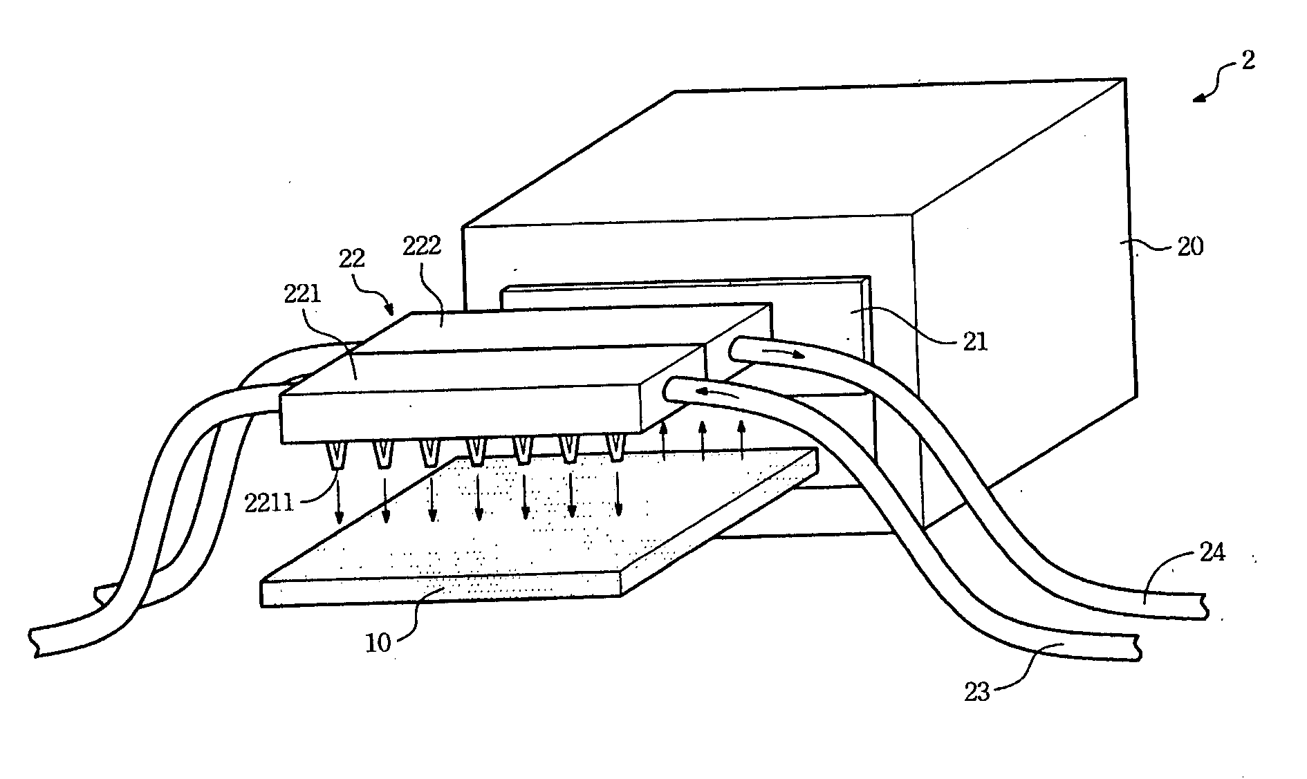
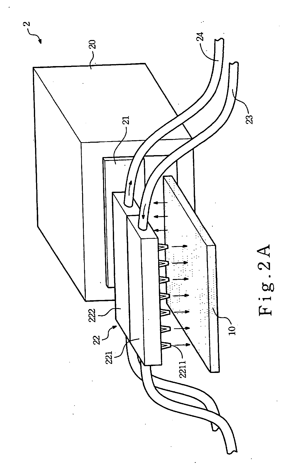
[0039] Referring to FIG. 2A, a preferred cleaning system in accordance with the present invention is structured as shown. The cleaning system 2, can be disposed in an etching machine for etching glass substrates 10 coated with photoresist.

[0040] Referring to FIG. 2B, it is a schematic diagram to show an action of the particle-removing device of FIG. 2A. As shown, the cleaning system 2 comprises a chamber 20, a gate 21, a particle-removing device 22, a gas piping 23 and a vacuum piping 24. The ...


PUM


Abstract

A cleaning system comprises a chamber and a particle-removing device. The particle-removing device, arranged outside the chamber, including an ionizer ionizing surrounding gas and spouting the ionized gas and a vacuum unit. Whereby, before an substrate is sent into the chamber, the ionized gas spouted from the ionizer neutralizes electrostatic charges and blowing up particles accumulate on the substrate and the particles are drawn away by the vacuum unit so that the object can be transmitted into the chamber much cleaner.

Description

BACKGROUND OF THE INVENTION [0001] (1) Field of the Invention [0002] The invention relates to a cleaning system and more particularly to the cleaning system that utilizes ionized gas to clean an object thereinside. [0003] (2) Description of the Prior Art [0004] In manufacturing a liquid crystal display (LCD), it is always an important issue to keep the glass substrate clean and to avoid the particles, which are the major sources of pollution, to contaminate the substrate. [0005] For example, the circuit pattern on a glass substrate of the LCD is formed by repeatedly performing photo engraving processes on a glass substrate. Typically, the process is performed by plastering the photoresist on the surface of the silicon film of the glass substrate, exposing the photoresist of the glass substrate through a photo mask with a predetermined circuit pattern, developing the hardened sensitized photoresist to remove the undesired part of the photoresist and finally forming the circuit patter...

Claims


Application Information

Patent Timeline
IPC IPC(8): B08B5/02B08B6/00B08B11/00B08B15/04C03C23/00H01L21/00H01L21/02H01L21/677
CPCH01L21/67236H01L21/67748B08B5/02B08B6/00H01L21/67196C03C23/006C03C2218/31G02F2001/1316H01L21/67028B08B15/04G02F1/1316
Inventor CHIN, CHIEN-HUNG
Owner AU OPTRONICS CORP
Why Eureka
Try Eureka