
Sealing structure by metal gasket

a technology of sealing structure and metal gasket, which is applied in the direction of engine sealing, cylinder, sealing arrangement, etc., can solve the problems of inconvenient manufacture, inconvenient maintenance, and inability to meet the requirements of use,

Inactive Publication Date: 2005-12-08
YAMAHA MARINE KK
View PDF11 Cites 12 Cited by
  • Summary
  • Abstract
  • Description
  • Claims
  • Application Information

AI Technical Summary

Benefits of technology

[0010] To inhibit corrosion of an engine with a metal gasket, a conventional rubber packing can be mounted simply on the mating face. In another application, an anticorrosive paste is applied on the mating face. However, in such an arrangement, reliable sealing can be compromised, for example, when removal of grease or dirt on the mating faces is insufficient and when there is irregular fastening forces of the packing and / or uneven application of the paste.
[0012] An aspect of the present invention involves providing a sealing structure through the use of a metal gasket that is capable (i) of meeting strict manufacturing, assembling and functional requirements necessary for a gasket, (ii) of securing a stable and reliable sealing property using a metal gasket with an electrolyte potential different from that of members of the engine to be protected, and / or (iii) of inhibiting corrosion of an engine.
[0014] Another aspect of the present invention comprises a sealing structure for sealing an interface between two members of an engine of an outboard motor. The sealing structure comprises a metal gasket that includes at least one opening for the passage of fluid through the sealing structure. The sealing structure also includes means for inhibiting the corrosion of the outboard motor about the opening.

Problems solved by technology

However, in such an arrangement, reliable sealing can be compromised, for example, when removal of grease or dirt on the mating faces is insufficient and when there is irregular fastening forces of the packing and / or uneven application of the paste.
However, the cylinder gasket disclosed in Patent Document JP-A-Hei 6-11042 has a particularly complicated structure comprising three layers and is difficult to manufacture.
Thus, to achieve the electrolytic effects due to matching in the electrolyte potential, existing gaskets of stainless steel are useless.

Method used


Image

  • Sealing structure by metal gasket
  • Sealing structure by metal gasket
  • Sealing structure by metal gasket

Examples


Embodiment Construction

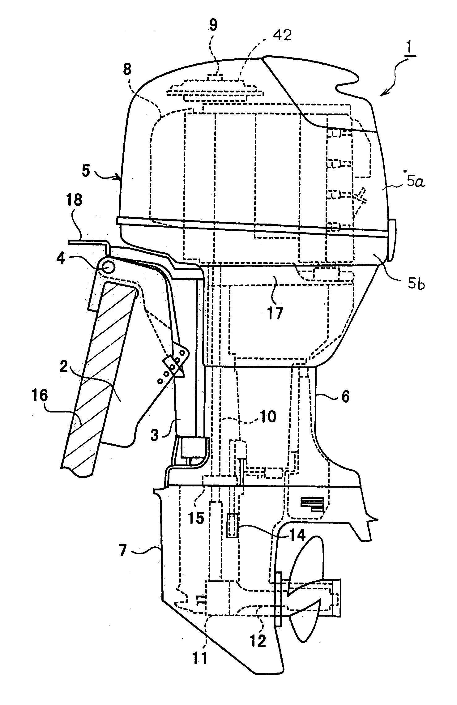
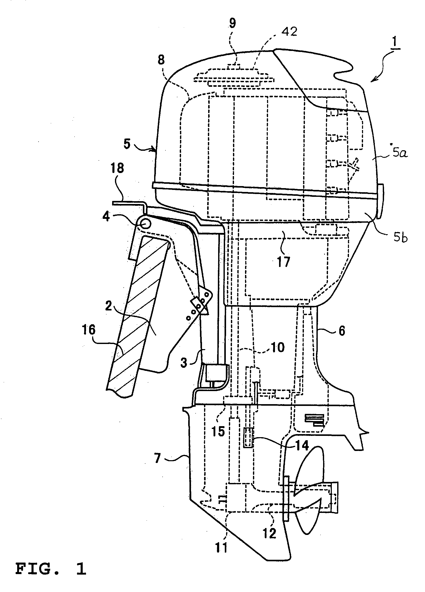
[0020]FIG. 1 is a side elevational view of an outboard motor 1 configured in accordance with a preferred embodiment of the present invention. An engine and drive train of the motor are illustrated in phantom.

[0021] As will be described in more detail below, certain embodiments of a sealing structure have particular utility in the context of a marine drive, such as an outboard motor, and thus the sealing structure is described in the context of an outboard motor. However, it should be appreciated that the sealing structure can be used with other types of marine drives (i.e., inboard motors, inboard / outboard motors, jet drives, etc.) and also certain land vehicles. Furthermore, the sealing structure can be used in a stationary engine for some applications as will be apparent to those of ordinary skill in the art in light of the description herein.

[0022] With reference now to FIG. 1, the outboard motor 1 is coupled to a transom plate 16 of a hull through a clamping bracket 2. The out...


PUM


Abstract

A sealing structure includes a gasket that has a passage for a cooling fluid that flows through a cylinder head and cylinder body of an internal combustion engine. The cylinder head and cylinder body are joined together at mating faces. The gasket is made of metallic material and is mounted between the mating faces P. The sealing structure includes an insulating elastic layer that is formed on the surfaces of said metal gasket. The sealing structure also includes a galvanic corrosion inhibitor that is applied to the contact portions of the metal gasket through the insulating elastic layer.

Description

PRIORITY INFORMATION [0001] This application claims priority to Japanese Patent Application No. 2004-143246, filed May 13, 2004, the entire contents of which is hereby expressly incorporated by reference herein. BACKGROUND OF THE INVENTION [0002] 1. Field of the Invention [0003] This invention relates to a sealing structure, and, in particular, to a sealing structure for an internal combustion engine. [0004] 2. Description of the Related Art [0005] When two different metals are physically or electrically connected and immersed in seawater, a small amount of current flows between the two metals. The electrons that make up that current are supplied by one of the metals, which gives up bits of itself in the form of metal ions to the seawater. This process is called galvanic corrosion and, left unchecked; it can quickly destroy underwater metals. [0006] Accordingly, various methods and devices have been developed to seal an interface between two metallic components that are coupled toge...

Claims


Application Information

Patent Timeline
IPC IPC(8): F02F11/00F16J15/08
CPCF02F2001/104F16J2015/0856F16J15/0825
Inventor KAMEYAMA, TAKUMA
Owner YAMAHA MARINE KK
Learn More